Basic HTML Version


Electrical protection and safety
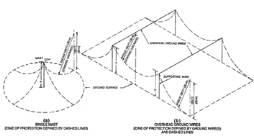
Comparison of the linear-sided cone and the
curved-sided zone of protection
Protection principles
Linear-sided cone of protection
The angle of protection surface from the horizontal varied from 450
for important structures to 300 for those of lesser importance. These
angles were to be used without regard to the height above ground.
These criteria were found to be inadequate, particularly for objects
more than 75 ft (22,86 m) high. Actually, very tall objects, such as
radio and television towers and very tall buildings, were found to be
struck below their tops by stroke paths coming from the side, although
the top of the structure was properly protected against the lightning.
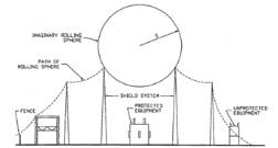
Curved-sided zone of protection
The zone of protection is defined by a sphere with a radius of 150 ft
(45 m), tangent to the earth or nearby grounded objects and touching
a protecting grounded (overhead) member or a lightning protection
air terminal. Rotating this sphere horizontally through 3 600 defines a
surface, and the area below this surface is the zone of protection. The
surface of a zone of protection is also formed when such a sphere is
resting on two or more air terminals. Objects within this zone have pro-
tection from 99,5% of direct strokes. It is necessary to analyse the zone
of protection for all directions around a structure to be protected, not
just one side. Corners particularly require protection, since these have
been found to be favourite targets for lightning stroke termination.
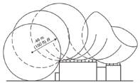
150 ft/ 46 m Rolling ball sphere for ordinary structures
Zones of protection [1]. The geometry of the structure shall determine
the zone of protection.
Principle of rolling sphere
For structures containing flammable liquids and gases, the radius of
the sphere of protection is reduced to 100 ft (30 m), instead of the
150 ft (45 m) dimension normally used [1].
Lightning protection guide checklist for
risk management
Key elements necessary for the protection of equipment
and personnel from lightning
• Use current division to control the dissipation of lightning strike
energy on an antenna tower grounding system through multiple
paths.
• Separate the antenna tower from the equipment building by a
minimum of 10 m/ 40 ft.
• Use only a single point grounding system for the equipment
building.
• Use a bulkhead panel/waveguide hatch for all coaxial cable entry
into the equipment building.
• Coordinate the location of the (1) bulkhead panel bond, (2) power
and telecommunications entry bond, (3) bond between antenna
and equipment building, at the single point ground connection.
• Isolate all wire-line communication services from remote ground
with optical devices or isolation transformers.
• Use ac power surge protection at main power entry and critical
secondary panels.
Who needs to use the recommended guide for the protec-
tion of equipment and personnel from lightning?
• To determine the potential for equipment damage or destruction
and personnel injury or death from a lightning strike, perform
the following risk evaluation. Count the number of bullets that
describe conditions at your location:
• Lightning damage has occurred here before.
• Personnel are located here and use the equipment at this location.
• This location is associated with an antenna tower that is within
50 feet/15 m.
• This location is in an area of the country that has 30 or more
thunderstorm days per year.
• This location requires ac power, and does not have surge pro-
tected power panels.
• This location requires wire-line telecommunication services that
have not been isolated using optical isolation or isolation trans-
formers.
• All equipment in this location is not bonded together at one single
point on the building grounding system.
46 m
(150 ft) R
S
Imaginary rolling
sphere
Path of rolling
sphere
Protected
equipment
(b)
Overhead ground wires
Zone of protection defined by ground wire(s)
And dashed lines’
(a)
Single mast
Zone of protection defined by dashed lines
Mast
Ground surface
Supporting mast
Overhead ground wires
Unprotected
equipment
Fence
Shield system
30 m
30 m
Radius 100 ft (30 m)
Radius 100 ft (30 m)
Radius 100 ft (30 m)
(Striking distance)
(Striking distance)
25
September ‘12
Electricity+Control