Basic HTML Version


B
A
A
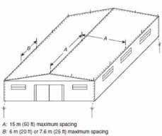
A: 15 m (50 ft) maximum spacing.
B: 6 m (20 ft) or7,6 m (25 ft) maximum spacing.
Electrical protection and safety
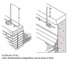
Air terminal height [1]
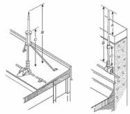
Air terminal support [1]
Air terminals on pitched roof [1].
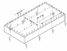
Air terminals on flat and gently sloping roof [1].
Such areas can also be protected using taller air terminals that create
zones of protection using the rolling sphere model so the sphere does
not contact the flat roof area.
Down conductors [1]
The location of down conductors shall depend on considerations
such as the following:
• Placement of strike termination devices
• Most direct coursing of conductors
• Earth conditions
• Security against displacement
• Location of large metallic bodies
• Location of underground metallic
• At least two down conductors shall be provided on any kind of
structure, including steeples
• Structures exceeding 76 m (250 ft) in perimeter shall have a down
conductor for every 30 m (100 ft) of perimeter or fraction thereof
A: 254 mm (10 in)
Note: Air terminal tip configurations can be sharp or blunt.
Air terminal height [1]
A: 600 mm (24 in)
B: Air terminals over 600 mm (24 in) high are supported.
C: Air terminal supports are located at a point not less than one
half the height of the air terminal.
Note: Air terminal tip configurations can be sharp or blunt.
A: 15 m (50 ft) max spacing between air terminals
B: 45 m (150 ft) max length of cross run conductor permitted
without a connection from the cross run conductor to the main
perimeter or down conductor
C: 6 m (20 ft) or 7,6 m (25 ft) max spacings between air terminals
along edge
Air terminals on flat and gently sloping roof [1].
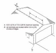
A: 0,6 m (2 ft) or 7,6 m (25 ft) maximum spacing
B: Air terminals are located within 0,6 m (2 ft) of
ends of ridges
Air terminals on pitched roof [1]
B
Electricity+Control
September ‘12
28