Click to download and read pdf
“At Eskom we have been doing ongoing research on the feasibility of replacing radiographic testing (RT) in our boilers with phased-array UT,” begins Eskom’s Level 3 NDT specialist and chief engineer, Grant Meredith.
“Radiography is written into the Pressure Equipment Requirements (PER) and it has its own acceptance criteria in the testing codes for boiler tubing. ASME has been pioneering, by way of code cases, the replacement of radiographic NDT results with ultrasound – more specifically, recorded UT – but there were no acceptance criteria that could be directly applied to recorded phased-array UT,” he continues.
“For piping with wall thicknesses greater than 8.0 mm, we found that phased-array acceptance criteria were relatively easy to establish, but then came the harder task of evaluating pipe in the 4.0 to 6.0 mm range, for which UT criteria were not yet incorporated into any of the codes. So, about five years ago, we began an investigation at Kendal Power Station to put together comparisons of phased-array UT results with radiographic imagery.
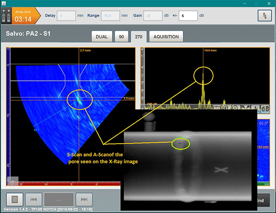
“Although becoming an acceptable replacement, in principle, we had to demonstrate that there was sensitivity compatibility between the radiographic films widely used at power stations and the new phased-array NDT data. In accordance with the criteria for radiography, when using phased-array UT, we had to prove that we could see an isolated volumetric pore as acceptable/rejectable at ¼ of the wall thickness if using the ASME Code or ⅓ of the thickness to comply with the ISO Code. This meant that, for a 6.0 mm wall thickness, we had to be able to reliably see a pore with a diameter of 1.5 mm,” Meredith explains.
Radiography is very sensitive to volumetric indications such as these, but less so with planar indications such as cracks or lack of fusion defects. The detection capability of the phased-array process, however, was found to be less adequate on the volumetric side while being better at detecting planar flaws such as cracks or lack of fusion defects,” he says.
“A C-scan on a modern phased array UT system gives a comparable visual result to a radiographic film. In addition, however, built-in digital techniques enable accurate sizing of both pores and crack-lengths from phased-array NDT data, which allowed us to directly compare radiographic and phased array results and detection sensitivities,” he explains.
A related part of the research was to use finite element analysis (FEA) and modelling to show the maximum pore size that would still be safe and fit for service if not detected. “Our task was to determine whether the limit of detectability for phased-array UT was acceptable for Eskom plant. We found, for example, that code requirements were oversensitive in their rejection criteria on volumetric indications, which was leading to us having to repair pores that posed no risk.”
Explaining how a radiographic image is generated, Meredith says that the source radiation is usually positioned slightly to the side of the weld being examined, with the film placed behind the tube. “When you look at the exposed film, you see the whole weld as an ellipse, with one half showing the front of the weld and the other half showing the back. The divergence of the gamma rays from the source creates a penumbra effect, so that the size of a pore on a film will look bigger than it actually is. For a pore sized on a film at 1.5 mm, when we cut that sample, we found that its actual pore size was nearer to 1.0 mm, hence our view that the radiography process overestimates pore size,” he explains.
“In addition to rejecting these welds because they measure outside of maximum code requirement on the radiograph, modelling by FEA analysis showed that, from a fitness for purpose point of view, actual pore sizes rejectable by code would have been acceptable to Eskom,” he adds.
By beefing up the sensitivity of the phased array UT equipment to detect a real 1.5 mm flaw, however, the correlation between the detected size and the measured size was found to be more accurate.
The bigger issue, however, is that cracks and lack-of-fusion defects can be missed by radiography and these pose a far greater rupture risk. This is because of the uncertainty and variability in terms of the plane along which these indications lie with respect to the radiation direction. Planar flaws beyond 15° of being in line with the source rays cannot be seen at all on an X-ray film, and these flaws are more serious than a 1.5 mm pore, Meredith says, noting that phased array UT offers far better sensitivity at detecting such flaws.
“The chances of missing a planar flaw that is outside a 30° cone on either side of the exposure direction is very high,” he reiterates. With semi-automated phased array, however, it is possible to detect a crack length and a through wall dimension of a planar flaw in
the orientation that they lie.
“Our findings in this regard are in agreement with research from The Electric Power Research Institute (EPRI) in the USA, which began to do some similar research some years back. Our recent research has gone a little further, however, and we have now published specific accept/reject criteria of our own that we can use alongside criteria being developed by the ISO Code. We intend to use these to produce an internal Eskom Standard, so that when we contract phased-array NDT service providers, we can give them clear and precise requirements about what is acceptable to Eskom,” he notes.
Eskom is also now in the process of drafting a phased-array inspection procedure for tube thicknesses of between 3.2 and 3.8 mm which, when complete, it intends to incorporate into qualification procedures for using phased-array UT during most of its scheduled boiler plant shutdowns.
“To properly qualify an NDT procedure, contractors need to do a performance demonstration that qualifies their system; their equipment; the procedure and their personnel, and this qualification standard is also now drafted.
Phased-array practitioners first need to demonstrate that they can detect known sized defects in manufactured samples. “We then give them blind trial samples to test before presenting a report on the findings, which need to closely align with what we know about the qualification samples. If successful, they will be qualified to do phased array inspection on our sites, but requalification will become necessary if their system; equipment; procedure; or personnel are changed in any way,” Meredith points out.
With respect to qualified companies with this capability and phased array personnel, he says that there are perhaps only 20 or so companies with this capability and, with only one or two qualified personnel in each company, far too few people with these skills are available. Hence capacity for these inspections is a limiting factor.
“We have an outage coming up now and we are looking at doing a complete radiography inspection with phased-array comparisons and we need 10 or so teams of 2 or 3 technicians to do this work.
“Ultimately, we believe that rather than being a ‘special’ process, phased-array UT will replace conventional UT as a mainstream inspection technique. We are therefore very pleased to see new Level 2 phased-array courses being introduced by training service providers such as the SAIW. In the near future, however, we also want to see phased-array technology becoming an integral part of all UT training courses and qualification programmes,” Meredith concludes.