Sollie Herbst, senior manager for Energy Systems at Zest WEG, presents an overview of the company’s mobile substation offering, highlighting their key use and the design principles that Zest WEG has evolved to ensure their ongoing success in Africa.
Click to download and read pdf.
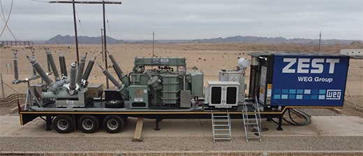 “A mobile substation is a fully equipped trailer or container with all the necessary high- and medium-voltage components that can be found in a permanent installation,” begins Zest WEG’s Sollie Herbst, who is the company’s senior manager for Energy Systems. This typically includes the power transformer; switchgear; metering equipment; transformers; surge arresters; protection and control equipment; along with the required ac (alternating current) and dc (direct current) operational supplies.
These systems are purpose designed as entire replacement units for the permanently installed substations supplying power from the high voltage (HV) transmission or distribution network – with voltages ranging between 33 kV and 220 kV – and delivering to medium voltage (MV) networks operating from 11 kV to 33 kV, he explains.
“Whenever there is a breakdown of a substation – due to natural disasters or if a plant is undergoing an upgrade or waiting for a permanent substation to be constructed – then a mobile substation can be relatively rapidly deployed to the site and connected to the network to supply interim power,” says Herbst.
“Mobile substations must be able to be moved quickly to supplement the demand. Their use requires no civil works, so response times can be rapid with limited dismantling and assembly onsite. They are easily connected to the existing electrical infrastructure and are generally designed as plug-and-play substitutes for permanent installations.
“Maximum mobility and flexibility are essential, so the systems must be able to be used in various configurations. They promote electrical network availability by reducing downtime durations associated with failures, maintenance and delays in constructing permanent infrastructure,” he tells MechChem Africa.
General considerations for design
Prior to starting on a design for a mobile substation, Sollie Herbst says the team must first understand the operational application and site conditions. The topography, the climate and elevations, for example, all need to be taken into consideration. “We need to understand the intended frequency of the unit’s relocation – once a year or once a month – because this changes the physical design,” he adds.
Other questions that need to be answered include: Will this unit be working from a provincial, rural or rural-urban environment? And are the sites on Government or private land? Does the trailer need to comply with road legislation, and which road legislation will apply? What are the road conditions, and the bridge height restrictions, on the routes? Where are the grid tie-in points? Is there sufficient access and enough space within the substation area?
“This is all very important to know in advance. In some cases on large units, we might have to partially dismantle the unit for shipping to site and then reassemble it once it arrives,” he explains. The availability of a suitable truck tractor in the region is also important, so the unit can be moved to a new location once the permanent substation is completed or repaired, he adds.
Other potential nearby applications for the unit may also come into play. “While customers tend to have a specific use in mind when making an enquiry, there may be follow-up uses within the area. Designs can meet these needs by including dual voltage selection on both sides of the power transformer, for example. That is, two different HV and MV settings and this gives more flexibility for interfacing to other utilities. Municipalities, mines, plants or communities in the vicinity can be incorporated, making a stronger and broader business case for the investment,” says Herbst.
High voltage side components and design
At the HV interface point of Zest WEG’s mobile substation is a connection to the available HV network. Here, suitably rated switchgear is used to ensure that the power can be connected and disconnected safely. Air insulated switchgear (AIS) can be used if space is not restricted, but gas insulated switchgear (GIS) or hybrid/mixed insulated switchgear is preferred. “Mixed technology has AIS and GIS combined in one unit. The long bushings are AIS, while the circuit breaker portion is GIS, which uses SF6 gas as the insulation medium to make it more compact,” Herbst explains, adding that GIS limits the amount of space due to the various HV switchgear components being incorporated in one hybrid unit. “This allows a lot more to be fitted into a smaller area, especially on the high voltage side,” he says.
He notes that other key considerations on the HV side include current and voltage transformers for metering, monitoring and trip protection; surge arrestors that can be designed for multi-ratio applications; and post insulators (PIs) to make sure the spans between conductors and other equipment are rigid enough to keep safe operating clearances at all times. “All these design choices are custom engineered, while easily retractable galvanised steel support structures are incorporated for ease of transport to site,” adds Herbst.
To meet the earthing needs, Herbst says each mobile substation has a full earth ring on the unit that gets connected to an earth mat at multiple points. Where earth mats are not already installed, an earth mat is buried around the entire mobile platform before being connected to the trailer structure; this minimises the risk of step and touch potential.
Power transformer considerations
For a mobile substation, reducing the dimensions and weight of the transformer is very important, Herbst notes. “The choice of the cooling system is the most critical aspect in this regard. There are a range of different types of cooling for transformers, starting with oil natural, air natural (ONAN). This typically results in a larger transformer because natural convection cooling is used, where the oil naturally circulates upwards into radiators and then back into the transformer core as it cools down. This is the conventional way to cool a power transformer,” he explains.
“A step above that, we have ONAF, which uses natural convection to circulate the oil, but the radiators are force-cooled using air. However, the oil direct, air force (ODAF) cooling system, in which the oil is force-circulated through the radiator by a pump, and then air-force cooled in the radiator, can deliver a 60% capacity increase compared to ONAN, enabling the weight and the footprint of the transformer to be significantly reduced,” says Herbst.
Other key transformer design innovations include polymer insulation on the bushings. In dual voltage applications, voltage selection taps on the primary and secondary windings via off-load tap selection switches that are accessible from ground level. And on the protection side, solid or partial earthing can be incorporated, depending on system requirements. An oil purification system and a digital gas analyser (DGA) can also be added to further protect and monitor the transformer.
Medium voltage system design
As with HV design, AIS, GIS or Hybrid switchgear can be incorporated on the MV side of the substation, and indoor or outdoor switchgear with surge arrestors can be considered. “In the scenario I am illustrating, we have one power cable coming in and one cable going out, but we can accommodate any supply scenario. For example, if a customer wants to feed to five different take-off points, we can include five metal clad switchgear breakers on the MV side. It all depends on the customer’s application,” he says, adding that provision can also be made for an external low voltage supply, should the need arise.
“In addition,” he notes, “If it's a dual voltage system, with two possible HV voltages and two MV voltage settings, we always build in a safety interlock system so it is impossible to make a mistake in selecting which voltage combinations to use.”
Trailer design
All Zest WEG mobile trailers that will operate on national roads are designed to satisfy the principal approval process required by relevant government legislation. Typically, pneumatic air suspension is preferred for mobile substations and trailer designs also accommodate manual raising and lowering of the travel height, depending on site conditions. Manual landing legs can also be deployed.
Trailers exceeding 14.5 m from the kingpin to the centre of the rear axles must be steerable if intended for use on national roads. The rear axles are automatically articulated hydraulically by the 5th wheel or, where required, manual steering can be incorporated.
Trailers can also be designed to incorporate oil catchment facilities and, due to the scarcity of specialised tyre sizes in many regions, the entire unit is designed based on standard truck tyre sizes.
“If a network operator or power distributor invests wisely in a Zest WEG mobile substation, the same system can be used again and again in several places, significantly reducing total costs of ownership.
“Our Zest WEG mobile substations are robust, reliable, well-integrated and compact solutions that can quickly be deployed and put into service – and when the unit is needed elsewhere, it can then easily be relocated,” Sollie Herbst concludes.