By Andrew Timmerman, Global Engineering Manager – R&D, Martin Engineering
Spillage in the loading zone of a belt conveyor can raise the cost of operation significantly – both from an efficiency and safety standpoint. The fugitive material piles below the system and clutters walkways requiring additional workers to clean it up thereby raising the cost of labour and causing a possible workplace hazard.
If not regularly addressed, the piles can encapsulate the belt and tail pulley, fouling the unprotected return side of the belt. A belt with material adhered to the underside leads to abrasion damage, mistracking and slippage, which increases the power requirements.
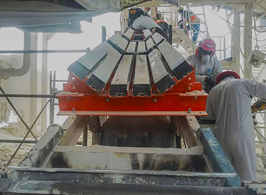
To avoid these consequences and mitigate belt sag, conveyor designers recommend constructing a sealed environment in the transfer chute. This can be achieved by reducing the distance between idlers or adding cradles. Cradles are slick urethane pads on a rigid steel frame that produce an even belt path which allows the rubber skirting to form a tight seal along the entire length of the chute. Not only does the cradle/skirting combination eliminate gaps, it allows for greater airflow control through the loading, settling and stilling zone for superior dust and spillage suppression.
However, a tight seal can induce additional friction. Although field tests have shown minimal erosion of the belting or splice, the seal calls for slightly more power, the ongoing cost of which is no small concern to operators. This article provides the calculations required to determine the distance between idlers to reduce belt sag. It will also discuss how engineers can calculate the power requirements of a cradle system.
Determining Sag and Idler Distance
In Belt Conveyors for Bulk Materials, Sixth Edition, the Conveyor Equipment Manufacturer’s Association (CEMA) recommends that conveyor belt sag between idlers be limited to 2 percent for 35-degree idlers and 3 percent for 20-degree idlers. The CEMA method refers to limiting sag outside the load zone to prevent spillage.
To fully prevent spillage, dust, premature belt wear, wear liner depreciation, and skirt seal wear in the load zone, the sag must be significantly less than that recommended by CEMA. For example, using the CEMA method results in a recommended maximum sag between idlers of 12.5 mm (0.5 in.) for 35° idlers and 19 mm (0.75 in.) for 20° idlers [Figure 1]. For loading zones with many gaps and tons of material escaping from the chute, field tests have shown that this is clearly unacceptable sag for control of fugitive materials in the load zone.
Sag (ΔYs) is proportional to the weight (force) of the belt and bulk material (Wb + Wm) [Newtons (lbf )] and the idler spacing (SI ) [millimetres (in.)], and is inversely proportional to the minimum belt tension in the load zone (Tm) [newtons (lbf)]. [Figure1]. To control fugitive materials, designers should consider managing the belt tension and idler spacing in the load zone to keep belt sag at no more than 3 mm (0.12 in.) and preferably 0.0. Even with very little sag, if belt support is not continuous, fugitive materials can escape and cause wear.
The example in Figure 1 shows that, with idler spacing of 600 mm (24 in.), there is 3.37 mm (0.135 in.) of sag. If the idler spacing in the example is reduced to 178 mm (7 in.), the belt sag drops to 1.0 mm (0.039 in.). On the other hand, if a belt-support system such as an impact cradle or air-supported conveyor section is used, idler spacing (SI) can be assumed to be 0.0. The calculation then yields belt sag of 0.0, because there should be no sag when the belt is a continuous, flat surface.
Cradles and Power Requirements
Belt-support systems have a significant effect on the power requirements of a conveyor. Changes in belt support will have a particularly noticeable effect on short or underpowered systems. Conveyor designers should ensure there is adequate conveyor drive power available to compensate for the additional friction placed on the conveyor when calculating the theoretical power requirements of proposed changes in belt-support systems.
Added kilowatts (hp) consumption can be calculated by determining the added belt tension, using the standard methods recommended by CEMA. The coefficient of friction of the new (or proposed) support systems, multiplied by the load placed on the belt support from belt weight, material load and sealing system, equals the tension. There is no need to allow for the removal of idlers, the incline of the conveyor, or other possible factors, as estimates provided by this method will, in most cases, produce results higher than the power consumption experienced in actual use. In applications where a lubricant, such as water, is consistently present, the actual power requirements may be one-half, or even less, of the amount estimated through these calculations.
Conclusion
Additional power requirements and costs will seem minor when compared to the power consumed by operating with one ‘frozen’ idler or several idlers operating with a material accumulation. By implementing the proper belt-support systems, a plant can prevent the more costly problems that arise from the escape of fugitive material. Cleanup of spillage not only increases labour costs but, in lieu of unscheduled downtime, exposes workers to activities around and under a running conveyor, a major cause of injuries and death in bulk handling industries.
Testing has found that a well-designed system incorporates slightly elevated power consumption, required to prevent spillage, rather than suffer the much higher power consumption and greater consequences that arise from fugitive material. The costs for installation and operation of proper belt-support systems represent an investment and commitment to ongoing efficiency and workplace safety.