platinum
24
06.13
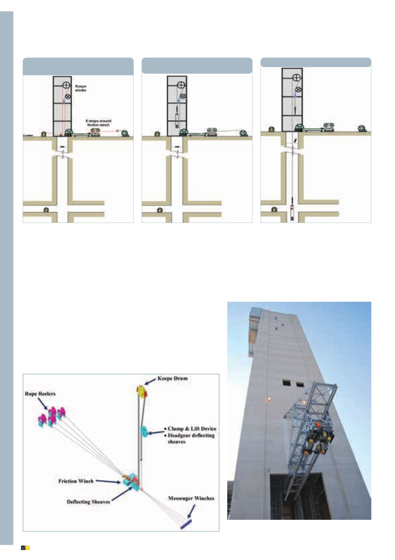
Step 1:
Reeve head ropes through
with messenger cable
Step 2:
Attach conveyance to head
rope
Step 3:
Lower conveyance to bottom
The headframe showing the crane used for cage changing. Note
the cantilever section at the top of the headframe.
ture. Rope life estimates were obtained from previous
studies of various configurations in Canada, Germany
and South Africa and maintenance costs were also
determined from previous studies.
“The results of the study showed that the Koepe
hoists offered favourable capital and operating costs
compared to the BMR option. The study also indi-
cated that the tower-mounted Koepe winders were
more cost-effective and offered more versatility for
the shaft bank area than the ground-mounted Koepe
winders,” Engelbrecht told
Modern Mining
. “Because
of limitations in rope technology, Koepe winders can
only be used to a depth of approximately 1 700 m
so – at around 1 680 m – No 16 Shaft was within this
limit. An interesting point is that Koepe winders have
a lower installed power, with a lower peak power de-
mand, than BMR winders – a result of the fact that
they have lower rotational inertia and less out of bal-
ance mass to accelerate. This was a significant decid-
ing factor back when the original choice was made
and is even more so now – more than 10 years later
– when there is an urgent demand for mines to cut
back on power consumption.”
For both Koepe options – ground- or tower-mount-
ed – RSV looked at the use of internal drive motors as
opposed to conventional overhung external motors.
It was decided to go with overhung motors based
on lower costs and simplicity and the fact that most
The rope-up sequence
is shown in the figures
above and opposite.
Rope-up equipment configuration.


