A
bbreviations
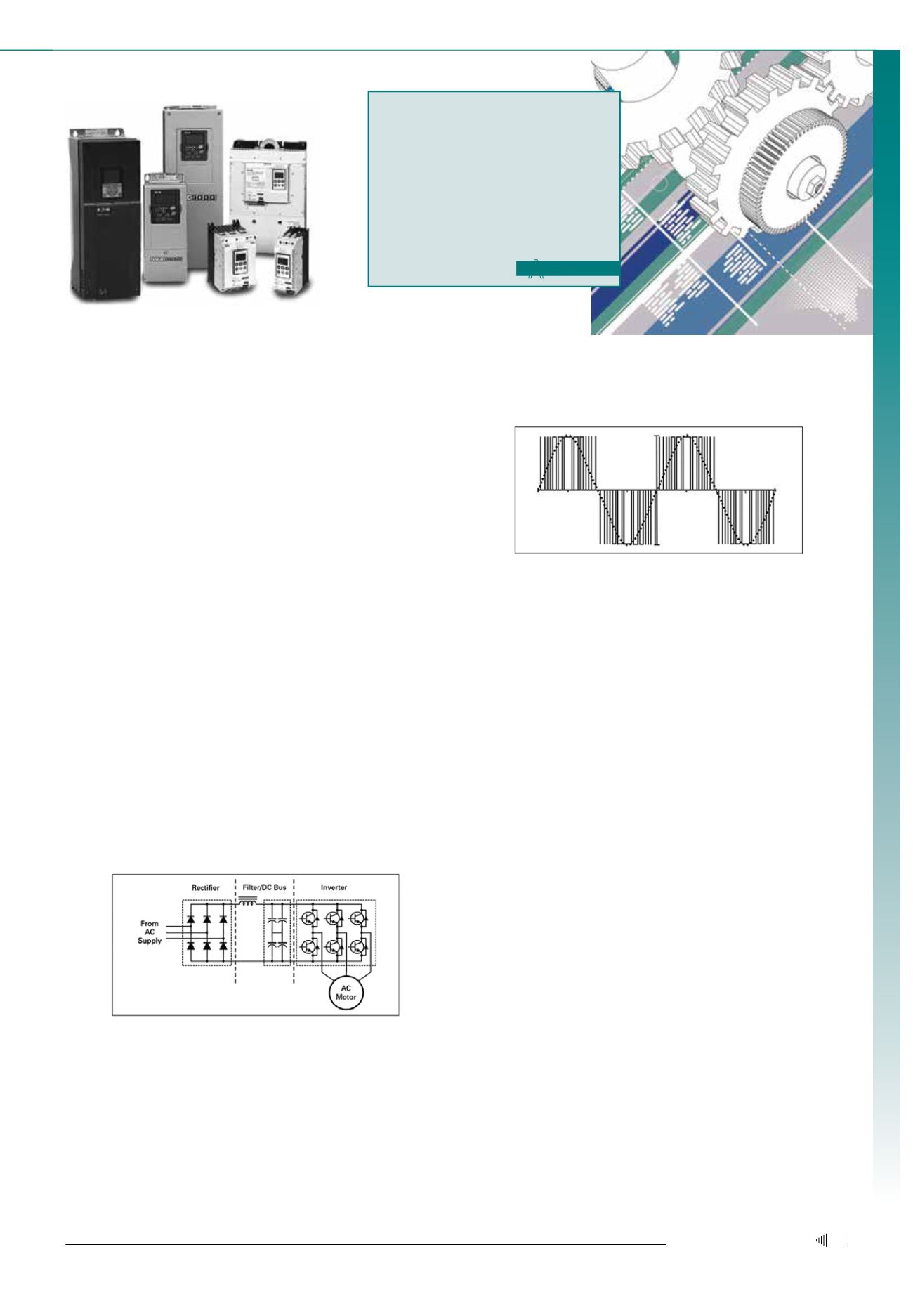
• Pulse Width Modulation (PWM): Switches the inverter semicon-
ductors in varying widths and times that, when averaged, create
a sine waveform.
Figure 3: Pulse Width Modulated Waveform.
Benefits of using aVFD
• Energy savings
• Reduces peak energy demand
• Reduces power when not required
• Fully adjustable speed (pumps, conveyors and fans)
• Controlled starting, stopping and acceleration
• Dynamic torque control
• Provides smooth motion for applications such as elevators and
escalators
• Maintains speed of equipment, making drives ideal for manu-
facturing equipment and industrial equipment such as mixers,
grinders and crushers
• Versatility
• Self-diagnostics and communications
• Advanced overload protection
• PLC-like functionality and software programming
• Digital inputs/ outputs (DI/DO)
• Analogue inputs/ outputs (AI/AO)
• Relay outputs
Energy savings
VFDs offer the greatest energy savings for fans and pumps. The
adjustable flow method changes the flow curve and drastically re-
duces power requirements. Centrifugal equipment (fans, pumps and
compressors) follow a general set of speed affinity laws. The affinity
laws define the relationship between speed and a set of variables:
• Flow
• Pressure
• Power
Drives, motors and switchgear
during the start and stop cycle, as well as throughout the run cycle.
VFDs are also referred to as adjustable frequency drives (AFDs).
Applications
VFDs are used in applications where:
• Complete speed control is required
• Energy savings is a goal
• Custom control is needed
How doVFDs work?
VFDs convert input power to adjustable frequency and voltage source
for controlling the speed of ac induction motors. The frequency of the
power applied to an ac motor determines the motor speed, based on
the following equation:
N = 120 x f x p
N = speed (rpm)
f = frequency (Hz)
p = number of motor poles
For example, a four-pole motor is operating at 60 Hz. These values
can be inserted into the formula to calculate the speed:
N = 120 x 60 x 4
N = 1 800 (rpm)
Figure 2: Function of a VFD.
• Ac supply: Comes from the facility power network (typically 480 V,
60 Hz ac)
• Rectifier: Converts network ac power to dc power
• Filter and dc bus: Work together to smooth the rectified dc power
and to provide clean, low ripple dc power to the inverter
• Inverter: Uses dc power from the dc bus and filter to invert an
output that resembles sine wave ac power using a pulse width
modulation (PWM) technique
Ac – Alternating Current
AFD – Adjustable Frequency Drive
AI/AO – Analogue Inputs/ Outputs
Dc – Direct Current
DI/DO – Digital Inputs/ Outputs
PLC – Programmable Logic Controller
PWM – Pulse Width Modulation
RVSS – Reduced Voltage Soft Starters
SCR – Silicon Controlled Rectifier
VFD – Variable Frequency Drive
5
July ‘13
Electricity+Control


