6
Chemical Technology • September 2013
mining & minerals processing
M
ost flotation cells comprise a pulp and froth
phase. The froth phase is used primarily for
three functions:
1. to create an environment for floated particles to
separate from the bulk slurry;
2. to allow selective concentration of the desirable
particles over non-desirable particles; and
3. transportation of mineral particles from bulk slurry
to the launder lip.
As the air is added to the flotation cell, bubbles rise
through the slurry, up through the froth to the exposed
froth surface, hopefully with product attached. Here it
expands and eventually overflows the launder lip.
As mentioned, transportation of mineral particles
from bulk slurry to the launder lip is one of the froth’s
primary functions. It therefore logically follows that
without a stable froth, there will be poor product trans-
portation to the launder lip, and hence poor recovery
and overall performance of the flotation cell.
The concept of the froth carry rate
Froth in a flotation cell is a combination of water, air
and solid particles. The froth itself is quite unstable
and you will often see bubbles breaking and coalesc-
ing into larger bubbles. Given this inherent instability,
it is important to realize that there are limitations with
how much material the froth phase can support and
transport to the launder lip in a given period. This is
termed the Froth Carry Rate (FCR), and is expressed
as t/m
2
h – the amount of material that 1m
2
of froth
can carry to the launder lip in an hour.
In a flotation cell the froth surface area is deter-
mined by the amount of froth crowding. Designing
a flotation cell with a low froth surface area, (high
degree of froth crowding), could lead to a situation
where too much material must be transported on the
available froth surface area, ie, a high FCR. In such
instances, the froth may collapse due to the relatively
high mass of the product rising to the top of the froth,
exceeding the amount of weight that the froth struc-
ture can support. This negatively affects transporta-
tion of concentrate from the cell, and therefore the
cell flotation recovery.
Conversely, designing a flotation cell with a high
froth surface area could lead to a situation where
Frothing at the lip
− stability in your flotation cell
insufficient material is present to stabilize the froth.
Solid particles are an important component of the froth
structure (Espinosa-Gomez,
et al
, 1998) and so too few
solid particles will also lead to low froth stability and
poor transportation of concentrate to the launder lip.
Sometimes it is possible to overcome this problem
by using a more resilient frother to stabilize the froth
phase. However, this has the negative consequence of
increased reagent consumption and higher operating
costs. Also, it can lead to increased water recovery,
which can cause a decrease in the residence time in
downstream flotation stages and a reduction in con-
centrate grade due to higher entrainment.
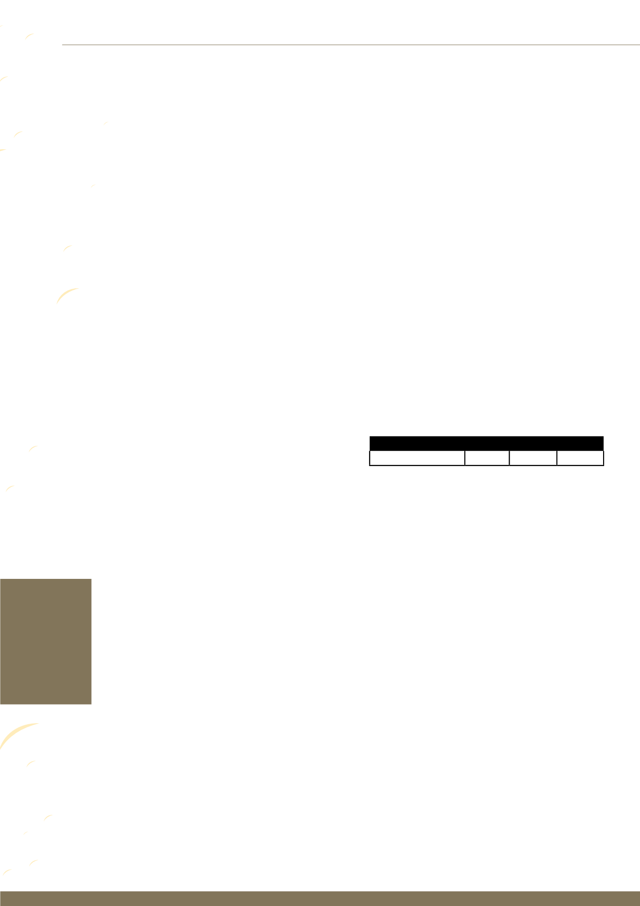
Duty
Rougher Scavenger
Cleaner
Froth Carry Rate (t/m
2
h) 0.8 - 1.5 0.3 - 0.8 1.0 - 2.0
The ideal froth surface area
As too high or too low an FCR has a negative effect on
froth transportation, effectiveness and flotation cell
performance, what is the optimum range? The answer
is ... it depends. Based on experience and analysis of
plant data, the recommendations shown in Figure 1,
have been published as acceptable FCR guidelines
from which to begin. (Bourke P, 2005).
The amount of froth crowding at the top of a flota-
tion cell determines the amount of froth surface area
for a given flotation cell. During the project design
phase, the optimum amount of froth crowding is
determined using design data from the customer
in conjunction with the accepted Froth Carry Rate
guidelines above, and experience of particular applica-
tions. By adjusting the size of the central froth crowder
(booster cone), as well as perimeter tank crowding
and the concentrate launders themselves, (Coleman,
R:
Output
2009), the froth surface area is adjusted to
an optimum level.
Problems with froth crowding
When there is too much or too little froth crowding,
this will lead to the FCR being outside the optimum
design range. Problems with the level of froth crowding
normally arise from one of the following reasons, or a
combination thereof:
by Jason Heath, Technology Leader – Flotation, Outotec, South East Asia region
Figure 1: Froth Carry Rate guidelines
This article was
originally published
in Outotec’s
newsletter, ‘Output
SEAP (South East
Asia Pacific)’,
August 2013 / 10
and is republished
here with kind
permission.


