Abbreviations
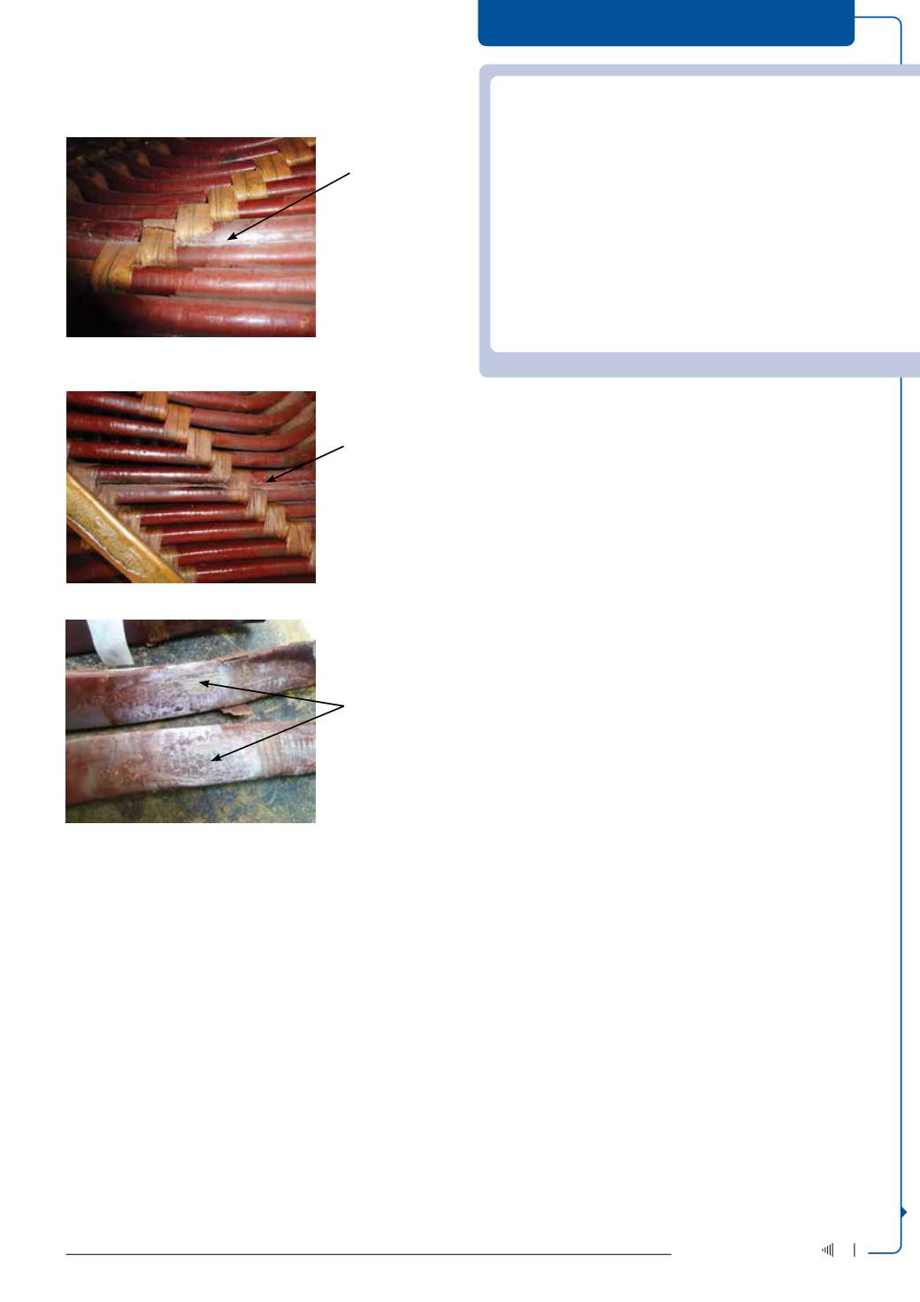
Figure 4: PD between coils in the overhang of an 11 kV motor (not many
years of service).
Figure 5: PD between coils in the overhang of an 11 kV motor (as in Figure 4).
Figure 6: Detail of damage to the insulation of coils from the motor in Figure 5.
Note: Figures 2 to 6 are frommachines connected directly to an 11 kV system
and not fed by a voltage converter.
Introduction to PD in LV motors fed from variable drives
Electric motors and speed control – HOW? A simple question – how
do we provide for, and easily allow for –manipulation of the torque/
speed curve of electric motors. Many years ago it would have meant
that dc motors were used for this purpose withmaintenance problems
associated with commutation, brushes, etc, or alternatively wound ro-
tor motors with associated controls, liquid starters, resistor banks, etc.
Times have changed. With the advent of power electronics we have
solid state fast power switching devices such as the IGBT (Insulated
Gate Bipolar Transistor) which introduce high voltage spikes every
time the dc voltage is switched to produce an ac voltage.
Types of machine insulation
• Type I
o Rated voltage
≤
700 V rms
o Random wound
o Not expected to experience PD activity during its life
Insulation in the Type 1 system is generally not PD-resistant. The con-
ductor insulationwould probably be an enamel covered conductor; the
wall insulation would be in the form of an insulation liner and, owing
to the random winding of the coils, it is possible that the beginning
and end of a coil would be next to each other.
A paper published by the IEEE entitled Partial Discharge Inception
Testing on Low Voltage Motors [4] reviews a manufacturer’s efforts
in testing NEMA LVmotor insulation for compatibility with adjustable
speed drives – Variable Frequency Drives (VFDs). PD Inception Voltage
(PDIV) measurements were selected as a tool to evaluate the future
performance of the stator insulation system to resist deterioration
by the drives.
Type 1 insulation systems discussed in the recently published
standard IEC60034-18-41 [2] are generally used in rotating machines
rated at 700 V (rms) or less and tend to have randomwound windings.
The procedures described in the standard are directed at:
o Qualification of the insulation system
o Type and routine testing of the complete windings of service
machines
Most drives convert the incoming sine wave ac voltage to a dc volt-
age then switch the dc bus voltage to construct a variable frequency,
variable voltage ac output voltage.
The dc bus voltage is switched many thousands of times per
second to create an ac wave form of the required frequency and volt-
age. The drive creates short rectangular pulses of fixed amplitude that
have various durations and frequencies. Virtually all modern VFDs
use IGBTs as the switching device; the dc bus voltage is dependent
on the rectified ac incoming voltage (50 or 60 Hz) supply.
The rise time of a PWM-IGBT drive is usually between 50 and
100 ns, with a voltage equal to the dc bus voltage. If the pulse takes
longer to travel down the power cable (that connects the drive to the
motor) than the rise time of the pulse, a reflection will occur at the
motor terminals which can (for a very short time) cause superposition
and thus a higher spike voltage than the dc bus voltage.
A figure of 0,15m/ns is quoted for the velocity of propagation
of a pulse along a power cable, which means that in a cable length
of 15 m the pulse would take approximately 100 ns. The amount of
overvoltage would depend on the surge impedance of the power
cable and the motor.
DRIVES, MOTORS + SWITCHGEAR
EF
– Enhancement Factor
GIS
– Gas Insulated Switchgear
GPS
– Global Positioning System
IEC
– International Electrotechnical Commission.
IEEE – Institute of Electrical and Electronics Engineers
IGBT – Insulated Gate Bipolar Transistor
IVIC – Impulse Voltage Insulation Class
LV – Low Voltage
MV – Medium Voltage
NEMA – National Electrical Manufacturers Association
PD
– Partial Discharge
PDEV – Partial Discharge Extinction Voltage
PDIV – Partial Discharge Inception Voltage
PWM – Pulse Width Modulation
rms
– root mean square
RPDIV – Repetitive Partial Discharge Inception Voltage
UHF
– Ultra High Frequency
VFD
– Variable Frequency Drive
Area in overhang
showing PD activity
(11 kV winding)
Gap between coils
insufficient and
not uniform. Too
close in certain
areas where large
voltage differences
occur
PD area in winding
overhang
11 kV winding
Gap between coils
insufficient and not
uniform. Too close
in certain areas
where large voltage
differences occur
Coils in section of PD
activity separated to
show damage caused
17
July ‘14
Electricity+Control


