Figure 7: Random wound stator showing how conductors could cross other
coils and even phases.
Figure 8: Random wound machine end winding showing conductors cross-
ing and overlapping resulting in areas which would be prone to PD activity.
Derivation of possible terminal voltages in service for
a converter-fed machine
Rated
Voltage.
V rms
Udc
V
Overshoot
Factor
U
p
/U
a
U
p
V
U
max
V
U
p
/
p
/U
max
500
675
1,1
743
409
1,82
500
675
1,5
1 013
409
2,48
500
675
2,0
1 350
409
3,30
500
675
2,5
1 688
409
4,13
Table A.1: Examples of maximum peak voltages (extract from IEC 60034-
18-41 [2]).
Where: Phase/phase voltage on the machine = dc link voltage x over-
shoot factor (1,1 -1,5 -2,0 -2,5)
Annex B (normative). IEC 60034-18-41 [2]
Derivation of test voltages for type 1 insulation systems
B6 Calculation of test voltages
As an example, the peak/peak test voltages for phase/phase and
phase/ground insulation in a 500 volt-rated rotating machine fed
from a 2-level converter are equal to the maximum operating voltage
shown in Table B.4 multiplied by the relevant total enhancement fac-
tor (EF) shown in Table B.2. The resulting voltages for the example
shown in Table B.4 are given in Table B.5. Table B.5: Examples of
maximum peak/peak test voltage for a 500 volt rated winding fed
from a 2-level converter, according to the stress categories of Table
4 and with a EF 1,25.
Stress Category or
impulse IVIC
Examples of maximum peak/peak test voltage
Phase/phase.
V
pk
/
pk
Phase/ground.
V
pk
/
pk
A (Benign).
2043
1430
B (Moderate).
2785
1950
C (Severe).
3123
2600
D (Extreme).
4641
3250
Table B 5: Example of Maximum peak/peak test voltages for a 500 volt fed
from a 2-level VFD (extract from IEC 60034-18-41).
In IEC 60034-18-41 [2]:
o Section 11 covers the type test procedure for Type 1 insulation
systems.
o Section 12 covers the routine tests with the note that tests de-
scribed in 11.2 1 and 11.3 are performed in agreement between
the manufacture and customer.
Problems due to and associated with the use of PWM
converters
o PD due to repetitive possible voltage overshoots in both MV and
LV machines
o Higher winding temperature due to reduced cooling at lower speeds
or heating due to harmonic currents (forced cooling could be a pos-
sible solution to loss of cooling due to reduced speed operation)
o Bearing damage due to induced voltages on the rotor
o Stress concentration at the slot exits and at junctions between
stress grading and corona protection materials
o Winding insulation ageing due to PD or dielectric heating often
intensified between turns as well as across the main wall of the
stator coils.
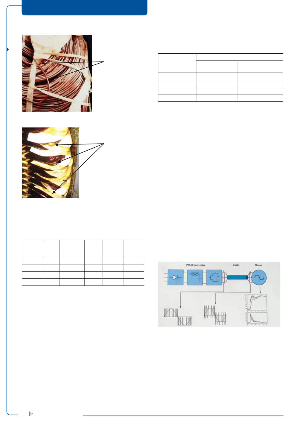
Figure 9 : Voltage overshoot and distribution along winding (typical).
Power electronic voltage waveforms affect the reliability of winding
electric insulation, if not designed correctly for the inverter supply.
Definitions and terms
• PD Inception Voltage (PDIV): the lowest voltage at which PDs are
initiated in the test arrangement when the voltage applied to the
test object is gradually increased from a lower value at which no
such discharges are observed
• Repetitive Partial Discharge Inception Voltage (RPDIV): minimum
DRIVES, MOTORS + SWITCHGEAR
Voltage stress in
between these
conductors, and the
rest of the winding,
could be very high
and is a potential
failure waiting to
happen, particularly
with VFD supply
Random wound
stator showing how
conductors cross
other coils in winding
Electricity+Control
July ‘14
18


