ROUND UP
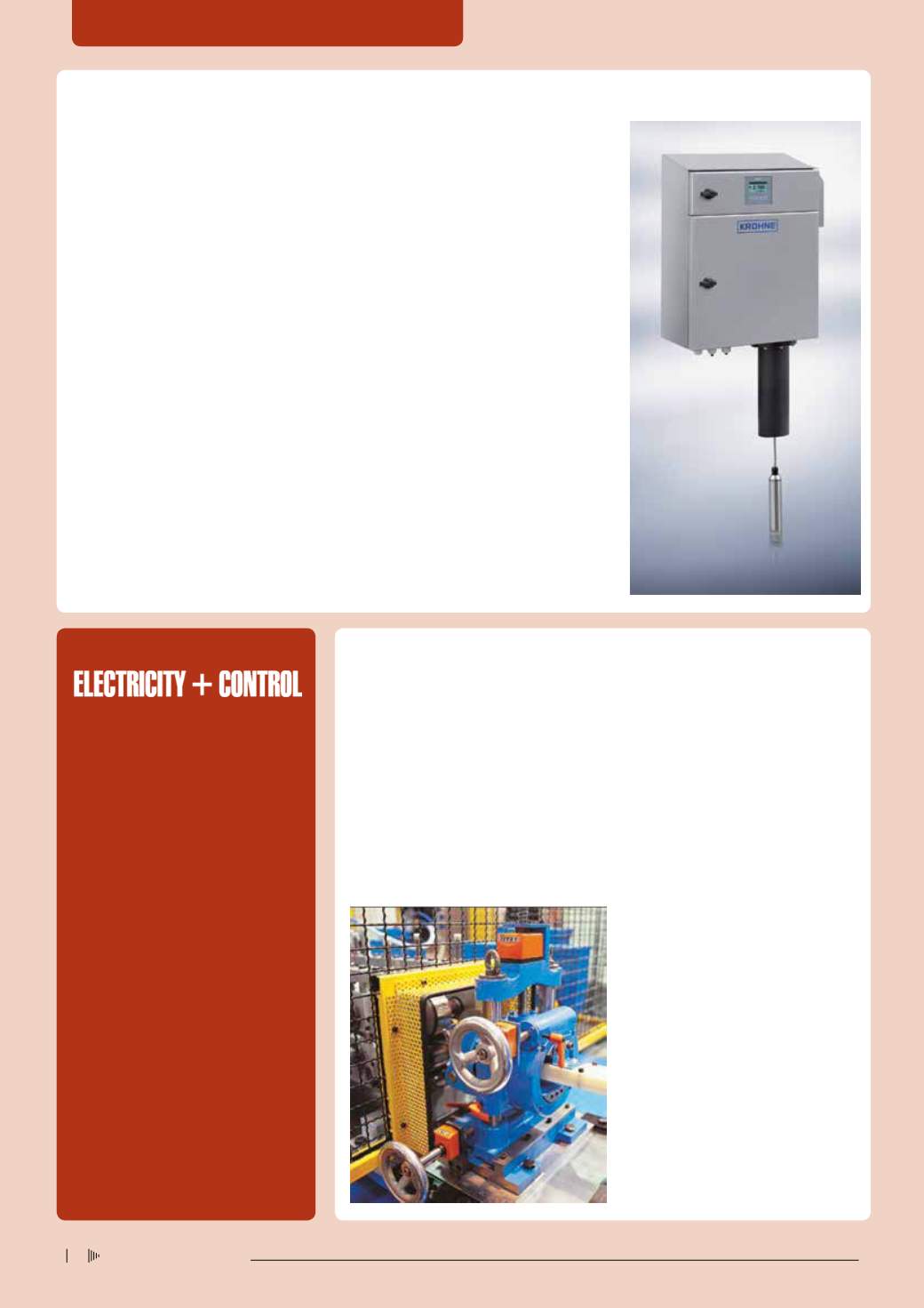
KROHNE
has introduced the OPTISYS SLM
2100 optical measuring system for sedimen-
tation profile measurement and continuous
tracking of sludge blanket. It allows for reliable
tracking of sedimentation layers in industrial
and municipal applications, eg in sedimenta-
tion basins of power plants, waterworks etc,
as well as sludge blanket measurement in
clarifiers and sludge thickeners in sewage
treatment plants.
OPTISYS SLM 2100 is the successor of
the OPTISENS OAM 2080 sludge blanket
measuring system, but has been completely
re-engineered to extend its area of application
to sedimentation processes. It uses a optical
suspended solids sensor, which is submerged
into the basin. Unlike ultrasonic-based sludge
level meters, the optical measuring principle
is not subject to echo returns from walls or
separating zones as well as signal damping
by fluff or floating sludge.
OPTISYS SLM 2100 is the first sedimenta-
tion measuring system to offer three measur-
ing modes: measurement of sedimentation
profile, two-zone monitoring and zone-track-
ing. For sedimentation profile measurement,
the system directly measures the suspended
solids concentration at all heights as the sen-
sor travels through all layers of the medium.
The two-zone monitoring feature enables to
monitor the heights of two predefined concen-
trations, eg fluff and sludge. It can be used to
prevent sludge washout into the next stage.
For continuous level measurement of a
predefined concentration, also known as zone-
tracking, the optical sensor moves within the
medium until it detects the concentration and
follows or tracks this zone continuously. This
can be used e.g. to monitor the change of the
sludge blanket level when de-pumping the
sludge. Here, OPTISYS SLM 2100 can replace
two measurements commonly used in this
application: with an ultrasonic level meter, dis-
turbances of sludge blanket can lead to false
measurements or even loss of signal for the
ultrasonic device. To compensate for this, an
additional turbidity measurement is installed
in the depumping line. Both can be replaced
by the new OPTISYS SLM 2100.
Enquiries: Krohne South Africa. John
Alexander. Email
o Control systems and automation
o Drives, motors and switchgear
o Standby and back-up
o Temperature measurement
o Transformers and substations
o Energy and enviroFiciency
For editorial submissions:
Wendy Izgorsek
– Email
For advertising queries:
Helen Couvaras
– Email
Heidi Jandrell
– Email
Tel. 011 622 4770
Position indicators are used in a wide range of sectors and for all production environments,
as almost all machines and systems feature guide elements, material stops or tools which
require precise and reliable positioning or alignment. The digital position indicators monitor
roller adjustment on sheet metal bending machines. The solid cast design of the counters
withstands the extreme mechanical influences under tough conditions such as those on
round sheet polishing machines, ensuring exact manufacturing.They are also suitable for a
wide range of wood-processing applications. Several work steps are often performed on a
single machine, panels cut and milled and edges glued and polished. Digital position indica-
tors are also used as adjustment aids in the metal, plastic and wood processing industries.
SIKO
’S mechanical digital position indicators are functional and highly adaptive by virtue
of the interaction of their variable gear ratios and unique modular roll indicator. Digital indica-
tors are an evolution of the handwheel with analogue displays. If users have to log several
rotations, it requires specific technology
with two pertinent features:
o A multi-digit display including a digital
point and fine reader for optimum reading
precision.
o A gear unit that can be customised to suit
individual requirements which ‘converts’ a
shaft rotation into an easily understandable
unit of measurement.
Position values can be monitored reliably
and directly on the shaft or spindle with the
original SIKO counters. The device slides
directly onto the shaft, and is secured in
place.
Enquiries: Pieter Deysel.Tel. 011 462 1920 or
email
Pin down the sedimentation process
Features – August 2014
Measurement and indication directly on the shaft
FLOW MEASUREMENT + INSTRUMENTATION
Electricity+Control
July ‘14
30


