SYSTEMS ENGINEERING
Abbreviations
GIS
– Geographical Information System
GNIS – Geographical Network Information System
GPS
– Global Positioning System
GRAP – Generally Recognised Accounting Practice
HV
– High Voltage
IFRS
– International Financial Reporting Standard(s)
LV
– Low Voltage
MV
– Medium Voltage
PNL
– Property/ Customer Network Link
SG
– Smart Grid
and state-of-the-art information systems in support of a largely
unqualified, data capture and modelling team. The engineers and
supervisors initially trained new data capturers and thereafter as-
sisted with ad hoc queries and interpretation of data where the data
capturers did not have the know-how.
Modelling software
Data modelling was carried out in a Geographical Network Informa-
tion System (GNIS) supporting real connected network modelling.
This greatly enhanced the modelling quality and added value to the
deliverable as a result of functionalities enabled from connectivity.
Most municipalities in South Africa maintain a GIS model which
simply represents the equipment location but does not include actual
connectivity that supports advanced functionality including captur-
ing and managing a Property/Customer Network Link (PNL), which
is of utmost importance for network operations as well as for smart
grid planning and implementation projects. The model implemented
allows full connectivity from the customer to any upstream device
though network topology.
The GNIS environment allowed for development of automatic
placement routines for template equipment which generated the
relevant equipment at the GPS location. As an example, a miniature
substation shown in Figures 1 and 2, consists of MV breakers, LV
fuses, a busbar, transformer and container. Using the office captured
attributes and the GPS position a complete and specific equipment
model is automatically generated in the GIS. This reduced the mod-
elling component to mainly establishing connectivity by connecting
networks between the equipment.
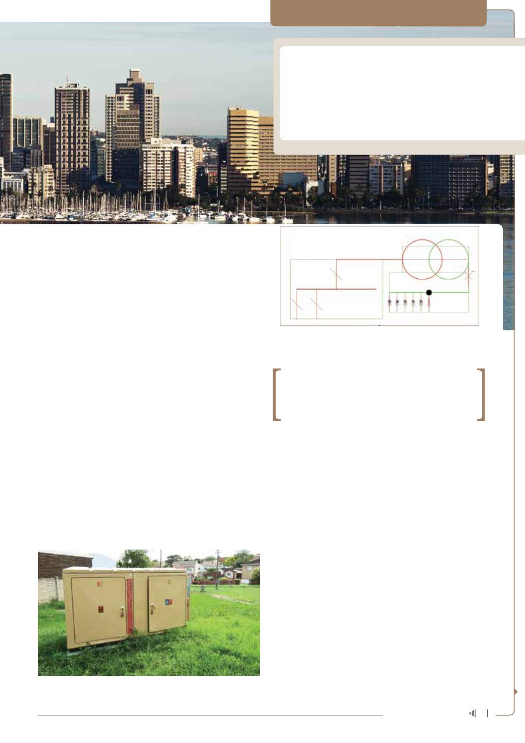
Figure 1: Mini-substation containing an 11 kV/400 V transformer, an 11 kV
ring main unit and LV circuit fuses.
Figure 2: Mini-substation connected network model, allowing for 11 kV
cable connections to an 11 kV ring main unit (left), the transformation from
11 kV to 400 V (upper right) and the connection to LV cable circuits at the
LV fuses (right).
Connected network model
Network modelling includes rule sets for connectivity enabling the
utility to trace and follow networks from the supply source to the client
connection adhering to actual network connectivity behaviour. This
approach tomodelling holds many benefits for the utility – it underlies
all network planning activities and is essential for network operations.
As such, GNIS is the application of choice for networked utilities,
including electricity, water, gas and telecommunications worldwide.
GNIS software presents a realistic view of the network in terms of
geographical location, how equipment connects to each other and
supporting technical data for engineering analysis.
As a result of GNIS modelling, the project not only recorded as-
set data, but also delivered logical information regarding the assets,
including:
• Network connectivity modelled from MV devices to LV networks
• Supply areas for devices is dynamic based on network open points
• Asset plant slot identification could be automated based on loca-
tion within network
• Network portions completed by datamodellers could be subjected
to various test routines to ensure data and modelling accuracy.
Connected network modelling is still a relatively new concept for
many local municipal GIS departments in South Africa which do not
model connectivity.
A different approach moved most of the attributed
capture work to office teams supervised by technical
specialists – reducing costs and enhancing quality.
33
July ‘14
Electricity+Control


