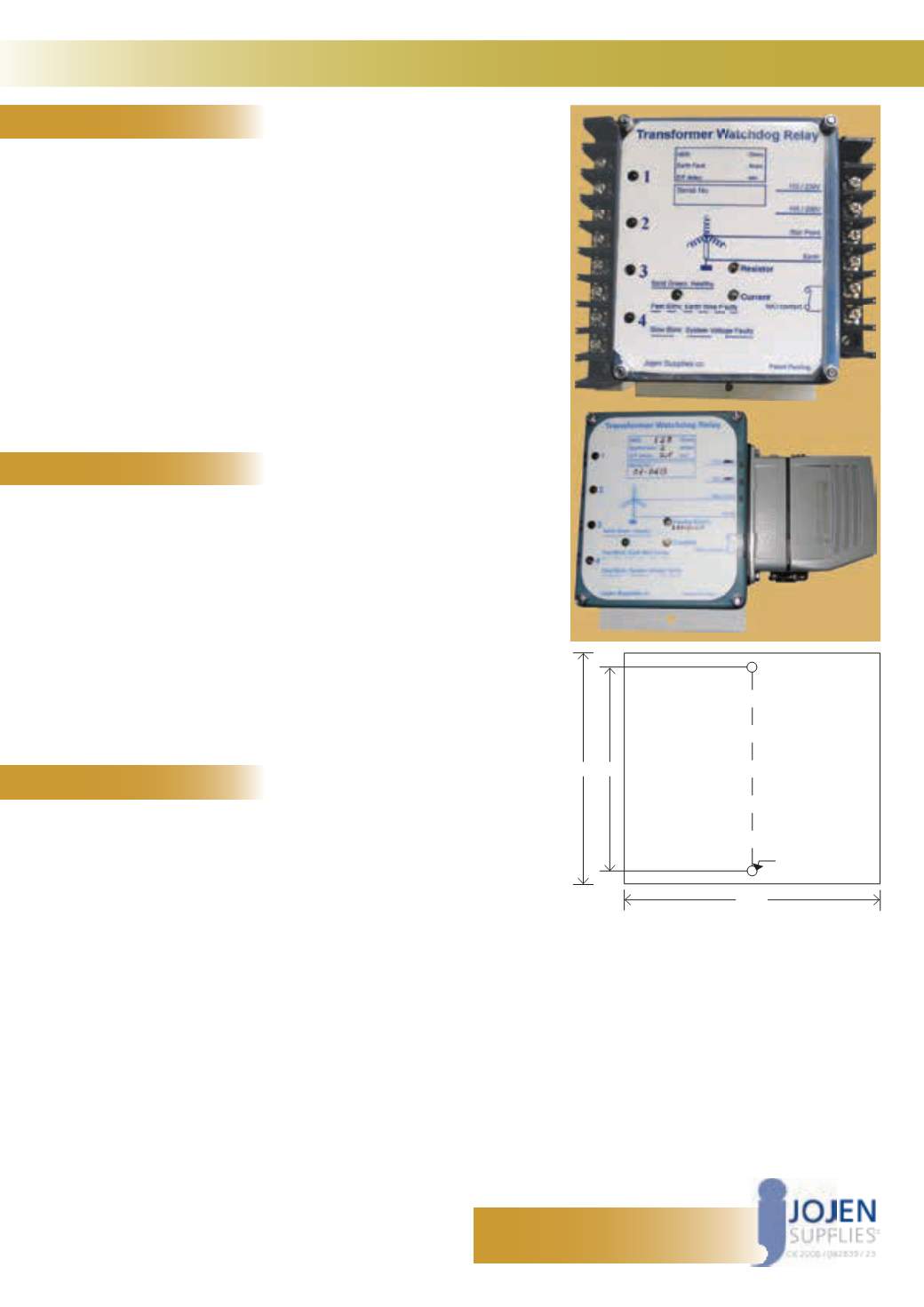
TWR: Transformer Watchdog Relay
FEATURES
Each of the 6 trip sources has its own indicator blinking 2-3 days without power
Continuous monitoring of earth bond integrity by measuring the resistance
between transformer star point (Neutral) and Earth
The Earth Fault current is calculated from two independent measurements:
the resistance of the Neutral Earthing Resistor (NER) and the 50Hz voltage
across it
Four independent isolated inputs for 110V from other contacts can cause
instantaneous closing of the N/O solid state output
Separate non-volatile LED-indication for each function
Trip times and levels for resistance and Earth Fault current can be pre-set for
discrimination
Separate LED indication for high/low-resistance trip and high earth-fault
condition
Separate LED indication for each independent input
LED indications continue for days after power is lost
Earth Fault current trip level and delay can be doubled by internal jumpers
Totally solid state and shock-proof
OPERATION
SPECIFICATION
Contact: John Warwick
Cell: 083 230 1610
E-mail:
A short burst of limited current and duration is applied to the local earth bond
approximately once per second
During this burst the voltage response at the earth bond is measured and
interpreted as resistance in Ohms. This is compared to an upper and optionally
lower limit
When the pre-set resistance limit is exceeded a solid state N/O output is
activated after a pre-set delay of 5 sec (default)
The output stays activated for up to 5 sec to allow sluggish breakers to operate
When any of the red LEDs is ashing and power is restored it will continue
ashing for approximately 5 sec after a healthy condition is detected
The green LED only lights up while the unit is powered and in the following ways:
– Solid Green LED = Healthy Earth Connection
– Fast Blink Green LED = Faulty Earth Wire or excessive Earth Fault current
is detected
– Slow Blink Green LED = System Voltage Faulty
Supply:
110Vac, single-phase 50Hz burden: approx. 3VA
Available in alternative voltages
Excitation:
3 pulses, 0.75msec at 200mA max every second
Continuous leakage: less than 1mA
Neutral – Earth max. voltage:
320V continuous
Resistance measurement:
Range: 0 – 150
Ω
, preferred trip settings: 27
Ω
, 63
Ω
Measurement resolution: 1
Ω
Accuracy: ±3
Ω
or ±5%
Default trip delay: 7 sec
Earth Fault current measurement (assuming NER=27
Ω
):
Range: 1 – 20A, default trip setting = 2A
Measurement resolution 300mA
Default trip delay: 2 sec
Trip delay for any of the four discrete inputs: 100msec
Internal watchdog to trip the output on internal failure: 0.5 sec
Trip output:
N/O solid state contact
Nominal switching voltage: 110 – 525Vac, 50 – 60Hz
Current rating: 3A continuous, 15A for 0.2 sec
Max.voltage between open contacts before clampdown: 600Vac
Normally open, leakage: approximately 3.5mA at 525V, 50Hz
Dielectric strength between contacts and Neutral reference:
2500Vac
Operating temperature range:
-5 to +70°C, Storage temperature range: -40 to +85°C
Overall dimensions:
160 x 173 x 60mm
Optional SCADA communication module:
Product-speci c data is available on request
160 147
Dimensions
complete with terminals
6D
173


