

Grant Meredith, chief engineer at Eskom until the end of 2019, has now set up his own inspection business in the UK. He talks to African Fusion about the advancements in NDT he has experienced since leaving South Africa.
Click to download and read pdf
 Having been a Certified Level 3 NDT Inspector for over 20 years – for industrial sectors from aerospace and power to oil and gas – Grant Meredith has been drawn to advanced NDT methods for his whole career.
“At Eskom I was responsible for NDT and looking into advanced NDT for the power utility’s fleet. In 2019, though, I was approached by APPLUS+, which was looking for a suitably qualified technical manager – someone with ultrasonic and eddy current NDT Level III and advanced inspection experience. They also wanted a bit of radiography knowledge and competence in all surface inspection methods. I was offe red a contract and, within five months, found myself in Australia,” Meredith recalls.
The position needed a cross-pollination of NDT technologies for clients upstream and downstream in the oil and gas industry, both onshore and offshore around Australia, and included taking care of contracts with Woodside Oil and Gas, Santos and Chevron. “My primary role as the company’s NDT Level III consultant was to maintain the technical authority status of APPLUS+ NDT services, with an overview of all NDT operations. This included a feed-in role to assist hands-on, where required, and to stay on top of advancing technologies that could be applied in the field.
“My Australian team and I were also responsible for pitching new technological advancements to our oil and gas clients, most notably to Woodside. We were tasked with developing advanced inspection methodologies that could improve efficiency, reliability, and detectability, while ensuring safe plant performance and more efficient testing for NDT personnel,” he tells African Fusion, before going on to describe some of the work he has been involved with.
Eddy-current array (ECA) testing
“Eddy current testing is a surface inspection methodology for surface breaking defects, primarily on conductive non ferromagnetic materials. An ac current in a coil is used to induce eddy currents close to the surface of the material. Any surface defect in the specimen disturbs the eddy currents and changes the impedance of the eddy current flow,” Meredith explains.
Much like conventional eddy current testing, each test coil in the array generates a secondary electrical current in the test component and, once the system is calibrated for the size and depth of detection requirements, an impedance change can be sensed by any of the coils. The extent of the impedance change, from cracks, corrosion or even heat treatment is then displayed as a 2D map-type diagram called a C-Scan as well as a 3D C-Scan showing discontinuity amplitude.
“I was initially looking at providing an eddy current testing solution using array technology. Similar to ultrasonic phased array technology where phased array UT has multiple transducers to cover larger areas in a single swept scan, an array of eddy current coils can be arranged into a single probe module and used to cover large inspection areas. Each coil communicates via various channels into one receiving unit and each indication can then be individually resolved to establish the overall condition– of an austenitic pipeline, for example.
“Using extrapolation, algorithms and analysis from all the data allows us to generate a single C-Scan overview of the surface condition, giving full length and breadth coverage of the test-piece surface,” he tells African Fusion.
“The benefit is that, instead of testing one small area using conventional eddy current probes and multiple sweeps, you can cover a large area with an array of sensing coils. I was looking at pipelines for stress corrosion cracking (SCC) on 316 stainless steel in a marine environment, testing large surface areas for SCC on the client’s pipelines,” he notes.
“Typically, we will do a raster scan, along the length of the pipeline, to cover the entire circumferential area of the pipe, then the system can stitch different raster scans together to give full surface coverage. An NDT inspection team can typically cover 10s of m2 area per shift and 100s of m2 of area in an inspection campaign,” he says. “We can detect pitting defects starting from 0.2 mm in depth and 1.0 mm diameter on 316 stainless steel, which is at the limit of detection capability for chloride stress corrosion cracking (CSCC),” he adds.
Grant Meredith and his APPLUS+ team did the initial trials and then introduced this technology to Woodside Oil and Gas: “They started mapping their pipelines to get a fingerprint or a baseline scan. From this starting position, they then looked to track degradation with time, so that they were constantly aware of the pipeline’s surface condition in these extreme marine environments,” he says.
Pulsed eddy-current testing
“If you consider pipes and vessels with lagging, though, you can create some strange and humid environments, particularly in offshore and marine conditions. This is where pulsed eddy current testing comes into play. To use conventional eddy current testing, including ECA or Phased Array corrosion mapping, the lagging on the pipe must first be removed,” Meredith continues, adding that this led to a follow up project on the use of pulsed eddy-current testing that could offer a non-intrusive inspection alternative. “Pulsed eddy current systems can effectively penetrate through lagging to test the pipe surface underneath, which makes it a truly non-intrusive method for lagged pipes,” he explains.
Pulsed Eddy Current (PEC) is an electromagnetic inspection technique used to detect wall loss on ferromagnetic lagged assets. It provides a volumetric measurement based on the footprint size of the probe used and the standoff. The resulting pulse is converted into an average wall thickness measurement in the probe’s footprint area.
PEC generates a magnetic field by electromagnetic induction from the electrical current in the coils of the probe. The magnetic field penetrates through the stand-off: namely, lagging, concrete, insulation with a weather jacket or marine growth. When the signal is cut off after a pulse, it induces eddy currents in the inspection item. The rate of signal decay is then processed using an advanced signal processing algorithm, which is then displayed as an average thickness reading over the footprint of the probe.
PEC will tell you where the defects are, and you can then cut off the lagging in only that location if you need to size or repair them,” he explains. “More to the point, if you test using a smaller footprint probe, you are able to detect a smaller discontinuity. If the probe footprint is bigger, it becomes more like looking for a needle in a haystack. If looking for pitting, you are not going to find it, but for corrosion patches, like ‘lakes’ – generally defined has having a three to one area to depth ratio – then pulsed-eddy current will find it,” he adds.
In summary, he says the detectability is different, but PEC can give a good overview of where problems might be and it is a “great technology for mapping the condition of an asset and giving an overall condition map”.
Also, though, Meredith says the method is not limited to pipelines. It is also ideal for vessels. “Pulsed eddy-current testing is starting to be used to support risk-based inspection (RBI) and is a great tool for the application of artificial intelligence (AI) and machine learning. It can be done while a vessel is online, lagged and at operating temperatures and pressures, and once the scan is done and the data collected, the vessel can be analysed with the results kept for track and trend purposes,” he informs African Fusion, adding that this allows NDT operations to be better aligned with engineering operations.
Long range or guided-wave ultrasonics
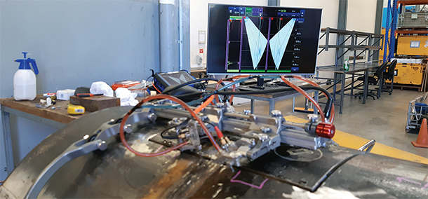
Another application of ultrasonic testing is using guided-wave ultrasonic technology. A particular application is using a ring coupled with sensor-receiver transducers, typically using clamps around the pipeline circumference. These transducers pulse and receive bulk waves, forwards and backwards along the pipe. “With the ultrasonic array built into a ring and clamped in a fixed position around the outside of the pipe, we are able to test for corrosion very quickly over long distances.
“A torsional ultrasonic wave is sent in an axial direction through the thickness of the full circumference of the pipeline under interrogation. The guided wave is sent in both directions and, depending on the type of fault being looked for, the coating and the condition of the pipeline, whether buried or above ground, and the bends in the pipeline, we can test lengths of 60 m in the forward and backward directions from the ring location on the pipe,” he says adding that the process is ideal for finding severe incidents of corrosion.
“The signal will be attenuated by pipe bends, buried pipelines and by various protective coatings, and in these cases, significantly shorter lengths of inspected pipeline in one scan are achieved. While it does not test welds, it does screen for general corrosion and corrosion under simple pipe supports over large distances. And any anomalous areas can be identified and quantified ,” Meredith adds.
Total focusing method (TFM) phased array
“For automated pipeline inspection on a circumferential weld, for example, you would often run tandem inspections using two sets of phased array probes. This automation allows for long sections of welds to be scanned in a single pass with all the data acquired for a weld in one test run. An advancement of phased array technology called the Total Focusing Method has taken inspection results further,” he tells African Fusion.
“This new phased array method involves a pitch-catch scenario. Essentially, all the ultrasonic sending elements on the array are fired at the same time, but while in traditional phased array UT the element that sends the signal is the one that that receives the return signal, with the total focusing method each transducer sends one pulse and return or echo data is collected by every other receiver in the array.
“If you have a 64 element probe, for example, every element fires one pulse and listens to 63 returning signals. The amount of data is therefore massively magnified. When you have a stacked defect, for example, you are able to resolve it with TFM, not by changing from the principle of pulse-echo, but rather by catching the signals coming from different angles and then extrapolating the path length and the time of flight of each signal to place the returning echo indication at an exact position relative to its location.
“The fundamental principles of ultrasonic testing still remain, it’s just about manipulating pulsed and received signals and using software to magnify and improve how the acquired data can deliver more detail,” he explains. “this is particularly beneficial when inspection is carried out on thicker parts with U-prep welds and when testing exotic materials”
“I stand by the principle that as advanced as companies want to go, one must always be able to take the inspection outcome requirement back to basics. Sometimes simple visual inspection or penetrant testing may provide the desired results rather than applying an advanced and often expensive inspection methodology. The first port of call is to keep the testing as simple and understandable as possible.
“The fundamentals for all of the inspection methods remain essentially the same but the application of advancing technologies improves these systems for clearer outcomes. We now also have drones to improve accessibility; and array probes to improve efficiency and sensitivity; and advanced connectivity and software for collecting and processing the data we acquire,” Meredith concludes.