


This article by Jürgen Arndt of WIKA outlines how continuous filter monitoring crucially influences the energy efficiency of a system and supports operators in complying with legal requirements.
Click to download and read pdf
 If the careful use of energy resources used to be for cost reasons, today, increased environmental awareness plays a role, and is becoming mandatory thanks to legal requirements and the quality of the technology.
Whether with air filters in ventilation and air-conditioning systems or oil filters in hydraulic circuits, increasing contamination of the filter element causes an increasing pressure drop. To keep the flow of the medium (air or oil) constant, the fan or the pump must apply more power, so the energy consumption increases.
Filter monitoring signals the increasing pressure drop across a contaminated filter element. Replacing a fouled filter ensures the flow of the medium and thus prevents the energy consumption of the fan or the pump from increasing.
Legal bases
With the adoption of the Kyoto Protocol in 1997, the European Union committed to reducing CO2 emissions. To reach this climate goal, in 2005 it adopted the EuP (Energy using Products) Directive. This was renamed the ErP Directive (Energy-related Products directive) – also known as the Eco-design directive, in 2009.
The directive aims to reduce energy use and other negative environmental impacts throughout the life cycle of products powered by electricity fossil or renewable fuels. The Directive means manufacturers must consider energy use and other environmental factors in product design and both manufacturers and importers are directly affected.
High resistance – high energy consumption
It is easy to understand that a contaminated filter element is more resistant to the flow of a medium than a new, clean element. Physically, the pressure in the filter inlet increases – which can be monitored very easily using a pressure measuring instrument – and this reduces the flow rate. Since the required flow is specified, more energy must be introduced to compensate for the restriction in the filter.
Energy-related vs cost-based considerations
From an energy perspective, a lightly soiled filter should be replaced straight away. This conflicts with the fact that the exchange itself generates material and labour costs. In addition, the exchange can only take place in the absence of both pressure and flow, and thus the machine or the process must be stopped. Based on these considerations, it is also clear that an exchange after a fixed period of use, as we are familiar with during annual services on cars, for example, is not an optimal solution.
The compromise is to identify an acceptable level of contamination specified via a maximum allowable differential pressure across the filter. Normal limit values for the differential pressure (ΔP) of hydraulic filters are between 1.0 and 5.0 bar. In ventilation systems, the limit values are between 50 and 5 000 Pa (0.5 to 50 mbar).
Regular monitoring of the pressure drop saves on operating costs, since changing out the filters only happens when the filter is close to reaching its accepted level of contamination. A further advantage is that through continuous monitoring and tracking, the filter replacement can be scheduled for the convenient and cost-effective shutdown time of the operational process.
In either case, the pressure drop across the filter is measured, that is, the change in pressure (ΔP) between the filter inlet and outlet. However, the pressure loss across the filter also increases with the volume flow.
The ΔP as an indicator of the contamination of the filter may therefore only be assessed in the defined operating state (average flow and temperature).
Filters for liquids can exceed the ΔP limit because of brief pressure peaks, for example. Due to inertia, however, these are not problematic issues for mechanical switches.
For sensors, however, it is advisable to provide for a short ‘dead time’ in the electronic control system to smooth out any transient measurements.
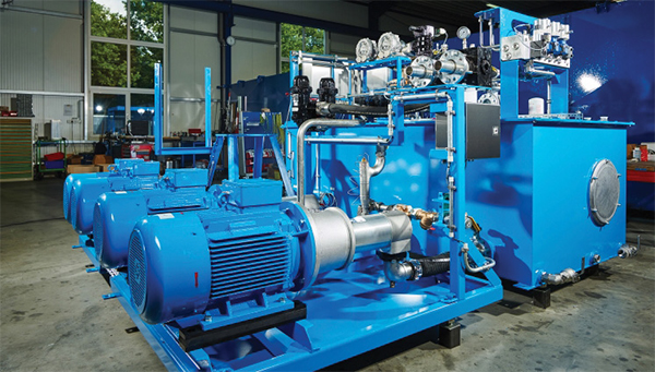
Filter monitoring in hydraulic circuits
The return filters in a hydraulic circuit are a special case. As the name suggests, these are in the return line, just before the oil flows back into the tank. There is ambient pressure (atmospheric pressure) in the tank. This means that ambient pressure is also present at the filter outlet. This simplifies monitoring since a differential pressure sensor can now take over the measuring task. This has a favourable effect on the costs of filter monitoring. First, differential pressure sensors are less expensive than ΔP sensor. Also, there is a saving on the need for a pressure line from the filter outlet to the low-pressure connection of the ΔP sensor.
In addition, temperature measurement of the oil is essential in hydraulic circuits. This enables the high viscosity of the hydraulic oil, which is still cold when starting, to be considered, thus avoiding false alerts.
The hydraulic oil temperature is also required to control the oil cooler. It has a significant influence on the time over which the oil is used.
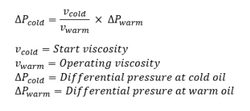
The formula for calculating excessive differential pressure due to the high viscosity of cold oil.
The trend in filter monitoring
From preventive maintenance to Industry 4.0 and IIoT cloud solutions, there is a demand for data everywhere. This can be seen clearly in the change from traditional measuring instruments with optical displays to electrical sensors with analogue or digital output signals.
When monitoring pressure filters, we see a trend to replace differential pressure sensors with gauge pressure sensors before and after the filter. This gives both the system pressure and the pressure at the outlet of the filter, which a differential pressure sensor does not offer.
The pressure drop, the difference between the two signals, is then calculated by the electronic controller, by the edge computer or in the cloud.
In addition to pressure sensors for filter monitoring, the WIKA portfolio covers all relevant measurement parameters that are necessary for controlling and regulating the operating states of a machine or system.
Further application examples can be found on our website in the ‘Industries’ pages.
www.wika.com/en-en/industries.