

By Pieter du Toit, Rheinhardt Sieberhagen and Liesl Burger, Photometry and Radiometry Section, National Metrology Institute of South Africa (NMISA).
Ultraviolet radiation (UV or UVR) is electromagnetic radiation with a wavelength shorter than visible light, but longer than x-rays, with focus on the non-ionising part of the UV spectrum (Figure 1). The International Commission on Illumination (CIE) subdivides UV radiation into three bands: UV-A from 315 nm to 400 nm, UV-B from 280 nm to 315 nm and UV-C from 100 nm to 280 nm [1].

Figure 1: The electromagnetic spectrum (not to scale).
UV radiation from artificial sources is used in many different applications. For example, UV-A radiation is used in the curing of inks, adhesives, and coatings as well as in liquid penetrant inspection for non-destructive testing (NDT). UV-B can be used in phototherapy for the treatment of skin diseases, such as psoriasis and vitiligo. UV-C is used in the disinfection method referred to as ultraviolet germicidal irradiance (UVGI) or germicidal ultraviolet (GUV), which can be used to disinfect various mediums such as air, water and surfaces. The basis of UV-C germicidal disinfection lies with the absorption of UV photons by a micro-organism’s DNA and RNA, leading to the photochemical destruction or de-activation of the DNA/RNA. At the same time, UV-B and visible radiation could re-activate or repair the DNA/RNA.
UV radiation can also present serious health and safety risks. Overexposure to UV-A or UV-B leads to sunburn. All ultraviolet bands damage collagen fibres and cause skin aging, and both UV-A and UV-B destroy vitamin A in the skin. Both UV-A and UV-B overexposure can lead to skin cancer [2] Overexposure of the eye to UV-C leads to extremely painful photoconjuntivitis and photokeratitis (inflammation of the conjunctiva and cornea).
UV radiometry
Ultraviolet radiometry is concerned with the characterisation and calibration of UV sources and detectors. The quantity in UV radiometry that is usually measured is the irradiance . Irradiance is the radiant flux or power in Watts [W] incident on a receiving element, divided by the area of that element in metre squared [m2]. The derived SI unit for irradiance is therefore W/m2, but other units commonly used for irradiance include µW/cm2, mW/cm2, and W/cm2, where 1 W/m2 = 100 µW/cm2 = 0,1 mW/cm2 = 0,000 1 W/cm2.
The irradiance per wavelength in nanometres [nm] is called spectral irradiance and is given in units of W/(m2.nm). The dose delivered onto a surface is determined from the product of the irradiance on that surface and the exposure time, which is given in (W.s)/m2 or in Joules per metre squared [J/m2]. Similar units such as µJ/cm2 and mJ/cm2 and are also commonly used: 1 J/m2 = 100 µJ/cm2 = 0,1 mJ/cm2.
Typically, broadband UV radiometers are used for the measurement of the effective UV irradiance produced by a UV source. The effective irradiance is determined by weighting the spectral irradiance of the source by the spectral weighting function (or action spectrum) for the actinic effect (phenomenon) of interest. For example, in the case of germicidal effectiveness this action spectrum could for instance be the IESNA germicidal spectral weighting function [3, 4]. Figure 2 shows the IESNA action spectrum and indicates that irradiance at around 265 nm is the most effective, whereas irradiance at 254 nm is only approximately 85 % effective.

Figure 2: IESNA germicidal action spectrum [IESNA].
UV sources
Figure 3 shows the relative spectral distributions of some UV sources. Low-pressure mercury (LPM) lamps are widely used for germicidal disinfection and peak close to 254 nm. Medium-pressure mercury (MPM) lamps emit over a wider wavelength range and peak at around 365 nm. Xenon arc lamps are also used for disinfection and in laboratories as UV sources for calibrations and testing because of their high output in the UV. UV LEDs which are quasi-monochromatic have also become popular and an example of the spectral distribution of a UV-C LED which peaks at around 270 nm is shown. Filters can be used to block unwanted radiation from the lamps, whilst the lamp envelope may also be selected to block unwanted radiation.
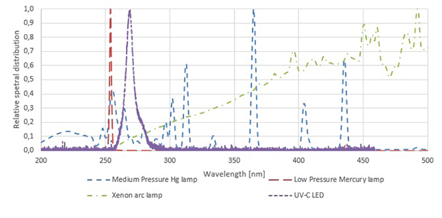
Figure 3: Relative spectral distributions of UV sources.
UV radiometers
A broadband UV radiometer usually consists of a few simple optical elements [5]. Figure 4 shows a schematic layout of a typical broadband UV radiometer. An aperture is used to limit the receiving area of the detector, which is usually a silicon photodiode. For irradiance measurements, it is important that the incident radiation overfills the aperture. A diffuser is used to ensure a cosine-corrected response to radiation coming in from different angles. A filter is used to select radiation from the spectral region of interest and cut off any unwanted wavelengths. Together, these elements determine the spectral irradiance responsivity of the broadband UV radiometer.

Figure 4: Schematic representation of a typical broadband UV radiometer.
The radiometer’s spectral irradiance responsivity is a function of the power responsivity of the detector, the transmittance of the diffuser and filter, the area of the aperture, the detector spatial uniformity, as well as the effect of the electronic circuitry. Depending on the radiometer circuitry the output can be a signal that is either read directly, amplified, or converted to an irradiance unit (e.g. W/m2) and displayed on the meter.
UV radiometer calibrations
The accurate use and calibration of these radiometers requires an understanding of the properties of the UV source and radiometer, the action spectrum of the effect under consideration (for example disinfection), as well as the measurement and calibration methods involved.
The calibration of a broadband UV radiometer [6] is carried out by determining its effective irradiance responsivity , defined as the quotient of its output signal and the effective irradiance . The output signal is the integral product of the radiometer’s spectral irradiance responsivity and the spectral irradiance distribution of the source, while the effective irradiance is the integral product of the action spectrum of concern and the spectral irradiance distribution of the source.
As an example, Figure 5 shows the integral product of an LPM lamp’s spectral irradiance distribution (red dashed line), centred at around 254 nm, and the spectral responsivity (blue dotted line) of a UV-C radiometer. The detector output Y is indicated by the purple area. Similarly, Figure 6 shows the LPM lamp’s spectral distribution (red dashed line) and the IESNA germicidal action spectrum (blue dotted line) and the sum of these products (purple area) gives the total effective germicidal irradiance. The output signal divided by the effective irradiance then gives the effective responsivity of the radiometer in units of reading/(W/m2).

Figure 5: Example of UV-C radiometer responsivity, low pressure mercury (LPM) lamp distribution and calculation of radiometer output.
 Figure 6: Example of germicidal action spectrum, low pressure mercury (LPM) lamp distribution and calculation of effective germicidal irradiance.
In the case where the output of the meter is in units of irradiance, the inverse of the effective irradiance responsivity, , is the meter’s correction factor, . This is the unitless factor that should be multiplied by the meter’s measurement result to give the actual effective irradiance.
There are three methods that can be used to calibrate a UV radiometer. The calibration method used depends on the equipment and calibration standards available, which could be source standards or detector standards, and the level of accuracy required.
1) Calibration using a source-based approach
To calibrate a UV radiometer, a source with a known spectral irradiance could be used as a reference standard. The radiometer is placed at a specified distance from the source with known spectral irradiance, and the effective responsivity is determined by comparing the meter reading to the calculated effective irradiance.
For this method, knowledge of the radiometer’s spectral responsivity is not required, but the calibration result is only valid for measurements of sources that have the same spectral distribution as the calibration source. If the meter was to be used to measure a source with a different spectral distribution to the reference or calibration source, a spectral mismatch correction factor should be determined, which requires additional knowledge of the relative spectral irradiance of the source being measured and the spectral irradiance responsivity of the radiometer.
These spectral mismatch correction factors can be quite large, leading to errors of up to 60 % if not applied [7], and it is therefore important to note the confined scope of application of this type of calibration.
2) Calibration using a detector-based approach
Substitution techniques can be used to calibrate UV radiometers when a calibrated reference radiometer is available. For example, the effective responsivity of the unit under test (UUT) can be determined by direct comparison with a reference radiometer in front of an application source. The reference and UUT need not have the same spectral responsivity, but the calibration is only valid for measuring sources with identical spectral distribution to the application source. For measuring other sources, the spectral mismatch of both the reference and the UUT must be known.
3) Full calibration method
The full calibration method requires a complete spectral irradiance responsivity calibration of the UUT, as well as a measurement of the spectral distribution of the source. The spectral irradiance responsivity of the UUT can be calibrated against a reference radiometer or detector [8]. Typical detector standards used as references for spectral responsivity calibrations include UV-enhanced Silicon (Si) and platinum silicide (Pt-Si) detectors (Figure 7).

Figure 7: Typical spectral responsivities of silicon (Si) and platinum-silicide (PtSi) detectors used as a spectral responsivity standards.
The spectral responsivity calibration requires a tuneable monochromatic source, such as a broadband light source and double monochromator, or a tuneable laser. The spectral irradiance responsivity of the UUT can either be determined directly by comparison to a spectral irradiance responsivity standard, or the relative responsivity of the UUT can first be determined against a spectrally calibrated reference detector and thereafter the absolute irradiance responsivity is determined at several wavelengths with an appropriate line source or with a laser to finally give the UUT’s spectral irradiance responsivity.
The measurement of the spectral irradiance of the source is also performed using the substitution technique. The irradiance of the unknown source is compared against the irradiance of a standard lamp using a spectroradiometer [9]. These standard lamps are typically either tungsten-halogen lamps (FEL) with a quartz envelope, or deuterium lamps in a precision housing. Figure 8 shows examples of the spectral irradiance distributions of a quartz tungsten halogen lamp at 50 cm and a deuterium lamp at 30 cm.

Figure 8: Typical spectral distributions of quartz tungsten halogen (QTH) and deuterium lamps used as spectral irradiance standards.
The final step in the calibration of the UV radiometer is then to use the spectral irradiance responsivity of the radiometer, the spectral distribution of the source and the action spectrum under consideration to calculate the effective irradiance responsivity. This full-calibration method requires sophisticated measurement equipment and standards usually only available in advanced laboratories and national metrology institutes (NMIs). It is the preferred method to use when calibrating a radiometer to be used as a reference device itself or where low uncertainties are required.
Summary
When using a UV radiometer, it is important to know what method was used to calibrate the radiometer and if the calibration is valid for the proposed use of the radiometer. For example, using a radiometer calibrated using a source different to the source to be measured (e.g. calibrated with an LPM lamp but used to measure an MPM lamp) will result in large measurement errors if the spectral mismatch correction factor is not considered. The calibration should preferably also be done at irradiance levels where the device will be used, since non-linearity of the radiometer can also lead to errors.
UV radiometers should also be calibrated in regular intervals. The exact interval depends on several factors including how the radiometer is used, the amount of UV radiation the radiometer is exposed to and if there are regulations prescribing the interval.
UV calibration uncertainties
The main contribution to the uncertainty during calibration is usually the uncertainty of the calibration of the standard lamp or standard detector. This is due to the inherent difficulty in measuring UV radiation of sources and the low response of detectors to radiation in the UV, respectively.
Some other aspects that contribute to the uncertainty when calibrating UV radiometers include out-of-band response (sensitivity of the radiometer to radiation outside of the UV region of interest), non-ideal cosine response and non-linearity of the UV radiometer. Drift in detector and radiometer standards due to exposure to UV also need to be considered. Positioning and alignment of the radiometer heads of both the UUT and reference radiometer (if applicable) also contribute to the measurement uncertainty. Temperature changes of the radiometers due to heating caused by the radiation source also need to be considered.
The non-uniformity and instability of UV sources add to the measurement uncertainty. For the measurement of UV sources, stray light and fluorescence must be avoided. If using single-monochromator or array spectroradiometers internal stray light can lead to large errors and corrections therefore need to be applied.
NMISA UV measurement capabilities
NMISA’s Photometry and Radiometry section maintains the national measurement standards (NMS) used for UV radiometry. The UV laboratory performs SANAS accredited calibrations of UV radiometers according to a detector-based method using working standard UV radiometers. These working standard radiometers are calibrated using the source-based method against calibrated UV sources.
The sources used as standards are calibrated in-house in the NMISA Spectroradiometry laboratory and all results are traceable to the national measurement standards for spectral irradiance. Other UV sources can also be measured in this laboratory.
Some of the working standard radiometers have also been calibrated for spectral responsivity by PTB (German NMI) and NPL (UK NMI) and these results are used to verify the radiometer effective responsivity using the full calibration method. The NMISA Radiometry laboratory can also currently perform spectral responsivity calibrations of UV radiometers against detector standards calibrated at PTB and NPL.
Additionally, the NMISA Spectrophotometry laboratory can perform calibration of UV filters and NMISA is currently piloting an international UV filter intercomparison.
Traceability
NMISA provides the South African industry with traceability to the international system of units (SI) and derived measurement units though maintenance of National Measurement Standards (NMS) (Figure 9). Comparability to other international NMS is ensured by participating in intercomparisons organised by the Bureau International des Poids et Mesures (BIPM), which is the inter-governmental organisation that coordinates the realisation and improvement of the world-wide measurement system between its member states. Furthermore, the NMISA Photometry and Radiometry section disseminates these units through calibration of instruments used in industry, either directly or indirectly through calibration laboratories, using methods developed by the CIE, which is recognised by the International Organisation for Standardisation (ISO) as the international standardisation body on all topics relating to light and lighting.

Figure 9: Traceability chain
Conclusion
The NMISA Photometry and Radiometry section is responsible for maintaining the national measurement standards (NMS) for UV radiometry in South Africa and disseminates this measurement capability to South African industries through calibration and measurement services.
The NMISA UV laboratory has recently acquired new equipment and standards including an automated three-axis calibration workstation and additional UV radiometers specifically for UV disinfection and UV hazard measurements. It can also perform spectral irradiance measurements of UV sources and the spectral responsivity calibrations of UV radiometers.
Staff can consult on a company’s UV measurement needs and are busy developing courses to assist industry in developing fit-for-purpose UV devices. NMISA is also continuously upgrading equipment to provide an improved service to industry.
Enquiries: pdutoit@nmisa.org
References
[1] CIE, http://eilv.cie.co.at. e-ILV (electronic International Lighting Vocabulary). 2014.
[2] ICNIRP Guidelines on limits of exposure to ultraviolet radiation of wavelengths between 180 nm and 400 nm (Incoherent Optical Radiation). Health Physics 87(2):171-186; 2004.
[3] CIE, CIE 155:2003 Technical Report on Ultraviolet air disinfection. Vienna, Austria. 2003.
[4] IESNA, IESNA Lighting Handbook, 9th Edition. New York, 2000.
[5] XU, G., HUANG, X. Characterization and calibration of broadband ultraviolet radiometers – methodology and uncertainty evaluation. Metrologia, 37, 235-242. 2000.
[6] CIE, CIE 220:2016 Technical Report on Characterisation and Calibration Methods of UV Radiometers. Vienna, Austria, 2016
[7] LARASON, T.C., CROMER, C.L. Sources of Error in UV Radiation Measurements. Journal of Research of the National Institute of Standards and Technology, 106, 649-656. 2001.
[8] CIE, CIE 202:2011 Technical Report on Spectral responsivity measurement of detectors, radiometers and photometers. Vienna, Austria. 2011.
[9] CIE, CIE 63:1984 Technical Report on Spectroradiometric measurement of light sources. Paris, France. 1984.

