


In 2015, Tenova company TAKRAF was contracted to supply the principal ore transportation system for Chile’s Chuquicamata mine: to move crushed copper ore from underground storage bins to a surface processing site. Mario Dilefeld of TAKRAF tells the story.
Click to download and read pdf
Owned by Codelco, Chile’s state-owned copper mining company and the world’s largest producer of copper and second largest producer of molybdenum, the Chuquicamata mine has been in operation since 1915. Over 100 years of open-pit mining have resulted in a mine that is some 1 000 m deep, 5 000 m long and 3 000 m wide. Once mined by drilling and blasting, the ore and waste material were transported to the surface by trucks for processing or disposal.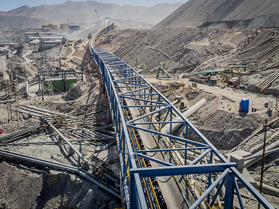
It has become uneconomical to mine deeper ore bodies using this process, however, and longer truck routes combined with a larger number of vehicles have resulted in high costs for vehicle maintenance and fuel, not to mention greater environmental pollution and safety concerns.
In 2015, TAKRAF was awarded the contract to supply a new conveyor-based ore transportation system for moving crushed copper ore from underground storage bins to the surface processing site. The system called for no redundancies, which means that for this project, high system availability, minimal system wear and easy maintenance of components were all imperative.
The project scope essentially called for:
- Removal of crushed ore from 60 m high underground storage bins with a conveying capacity of 11 000t/h.
- Transportation to the surface with a minimum number of material transfer points.
- Conveying from the underground tunnel exit to the existing processing plant whilst taking into account existing infrastructure (railway lines, mine roads, pipelines, etc).
- Ensuring high system availability, minimal system wear and easy maintenance of all components.
Storage bin discharge
The conveying system supplied by TAKRAF starts at the underground storage bin discharge point. Two material stores in the form of vertical cylindrical openings with a diameter of 6.0 m and a height of 60 m separate the flow of mined material from transport-to-ore processing. The use of conventional belt feeders was originally planned for controlled material discharge. With this conveying method, material is transported from the discharge area along a 30 m conveyor route to a transfer point using a flat belt with vertical chute sidewalls.
Optimisations made to the system after the contract was awarded, however, led to a change in the system. By employing a feeder conveyor, the conveyor belt now has a 45° trough angle along the entire conveyor route, with the only chutes being in the storage bin discharge area. As with a belt feeder, the contour of the material to be conveyed is specified by a shear gate and the flow of discharged material is defined by varying the conveying speed. The elimination of vertical sidewalls along the conveyor path means less wear and thus reduced maintenance costs, combined with energy savings of around 25%.
Transporting material to the surface
Two conventional trough conveyors connect the material discharge of the feeder conveyors with the loading point of the inclined conveyor, about 900 m away. Installed in a tunnel that extends some 6 400 m to the surface, the inclined conveyors overcome a not insignificant difference in elevation of 950 m. Each underground transfer point along the tunnel requires an underground chamber with a crane for maintenance work, power supply, transformers and electrical and mechanical drive technologies, with adapted ventilation and suitable access paths.
In order to minimise the number of transfer points, the inclined conveyor section was successfully developed employing just two conveyors. To achieve this feat, St 10 000 quality conveyor belts from ContiTech were used for the first time; they employ newly developed components that redefine the performance limits of belt conveyor technology. Operating belt safety ratings of S=5.0 required belt connections with a reference fatigue strength of over 50%. This value was proven on the belt test rig at the University of Hannover in Germany.
In addition, new high levels in terms of installed drive power of 10 000 kW per drive pulley and 20 000 kW per conveyor were achieved. In cooperation with the drive motor manufacturer, ABB, TAKRAF engineers developed a drivetrain consisting of 5 000 kW synchronous motors and membrane couplings to connect the pulley and rotor shafts.
Complete and fully-assembled factory-tested motors were delivered to site so that no motor assembly had to be performed in the dusty environment.
A simple alignment and motor air gap adjustment system was used during installation of the drive and this enables simple readjustment in the event of motor air gap deviations from the setpoint. Maintenance of the air gap between the rotor and stator is a crucial requirement for the operation of the motors. The air gap, which is 14 mm, must only be allowed to deviate from the setpoint within small tolerances. Deviations in the air gap reduce the efficiency of the motor, and if rotor and stator were to make contact with each other, this would damage the motor. The air gap itself is continuously monitored during operation. If deformations and/or subsidence in the steel structure or in the motor foundations lead to a deviation in the air gap setpoint, the stator has to be realigned. To simplify this process, the spacing between the rotor and stator at the non-driven end of the motor was fixed by a support bearing.
A membrane coupling also compensates for the deformation of the pulley shaft caused by belt tension. The adjustable motor frame facilitates alignment of the motor during installation and ensures simple realignment if necessary. Eccentrics and spindles allow the stator to be adjusted in all directions.
In the event of an accident, a simple separation system for disconnecting the pulley from the motor has been installed to ensure continued operation of the system for a short time with a reduced number of drive motors. Should a motor fail, it can be quickly moved into a disabled position by opening the membrane coupling and adjusting the spindles. The system can then continue to operate with reduced power.
Connecting the underground tunnel to the existing processing system
The landscape surrounding the processing plants has been shaped by over 100 years of mining at Chuquicamata. In addition to the various processing systems, waste heaps, train tracks, roads, pipelines and buildings scar the landscape. The challenge for the new conveyor system was to design a system that took into consideration this landscape for its entire length, from the end of the underground tunnel to the processing plant more than 5.0 km away.
A continuous single flight conveyor with the following notable features was developed:
- A point to point distance of 5 330 m between the material loading point and material discharge with a height difference of 287 m.
- Horizontal curves with tight radii (1,600 m to 2,300 m) on more than 60% of the conveyor length.
- Approximately 50% of the conveyor length is on elevated structures with variable lengths adapted to local conditions and foundations positioning and with support intervals of up to 96 m
The conveyor design again revolved around ensuring high system availability, minimal system wear and easy maintenance of components. All loading points along the conveyor route were optimised to reduce conveyor belt wear. The arrangement of the rock boxes and grizzly fingers was verified with simulations using the Discrete Element Method (DEM).
Newly designed transfer chutes allow wear plates to be replaced quickly and easily. To replace idlers, a specially designed TAKRAF maintenance vehicle is able to travel along the conveyor path, enabling the conveyor belt to be lifted and worn idlers to be safely and efficiently replaced. At the material discharge point, a bunker building performs a limited material storage function. Two feeder conveyors remove the material and feed it to the processing plants.
Three 5 000 kW direct drive motors drive this conveyor, and a St 6 800 conveyor belt with a belt safety of S=5.1 is used. Vibration behaviour of the belt during start up and braking was analysed across all operating conditions using dynamic belt calculations.
In conclusion, the St 10 000 conveyor belt with its 20 000 kW of drive power per conveyor redefines the limits of belt conveyor technology, making it possible to reduce the number of underground transfer points.
High system availability, minimal system wear and easy maintenance were essential criteria when designing this system, resulting in numerous innovations, six patents and a modern, powerful and environmentally friendly conveyor system. As an added bonus, highly efficient electric drive motors have now replaced diesel trucks, reducing CO2 emissions for transporting material by more than 66%.