
The importance of surge protection in countries with relatively high lightning activity such as South Africa is essential. However, it is usually overlooked with the installation of a new electrical system or during the upgrade and maintenance of an existing electrical system. This is usually due to a general lack of understanding of the risks, as well as overwhelming specifications, ratings and stringent requirements causing confusion for the installer.
 Surge Protection Devices (SPDs) are classified as either Type 1 or Type 2 tested devices (Type 3 exists as well), which is clearly indicated on the device itself as per the requirements from SANS 61643-11, the latest SPD testing standard. An illustration of this is shown in Figure 1. Common questions usually raised are “What does this mean?”, “What is the difference?”, and “How are they used?”.
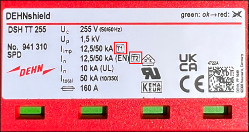
Figure 1: Type 1 and Type 2 indication on SPD.
There is an important difference between direct lightning current, also known as impulse current, and surge current. The less common impulse current enters an electrical system by direct injection of lightning through a dedicated lightning protection system or direct strikes to electrical lines. Surge current is an induced, secondary effect from a nearby lightning strike up to 2km away from a structure. The basic difference is shown in Figure 2.
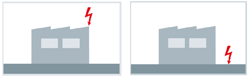
Figure 2: Difference between direct lightning strikes and surges
Impulse current is described with a test waveshape known as 10/350µs and surge current with a test waveshape known as 8/20µs. Figure 3 below shows a basic illustration of these test waveshapes. In the impulse current wave, the impulse will reach its peak current value, measured in kA, in 10µs and decays to 50% of this value in 350µs. In the same manner, surge current reaches its peak value, in kA, in 8µs and decay to 50% of this peak value in 20µs. Due to the longer duration of the impulse current waveshape, much more energy is involved and thus requires stronger surge protection devices to mitigate this in comparison to induced surge current.
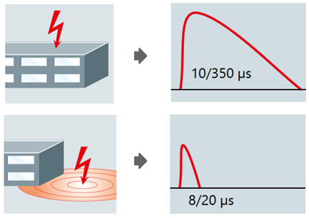
Figure 3: Meaning of 10/350µs and 8/20µs.
How do we know when we need an external lightning protection system and stronger SPDs or if we only need an SPD for induced surges with no lightning protection? To determine the likelihood and number of direct lightning strikes and induced surge events for a specific structure, a calculation known as a Lightning Risk Analysis is conducted as per the probability calculation methods from SANS 62305-2. The latest wiring code uses a simplified method of this calculation for practical purposes. If the risk of regularly experiencing direct lightning strikes is presented, it is recommended to install an external lightning protection system, typically a mast or dedicated air-termination rods, down-conductors, and an earth-termination system. These external lightning protection systems must then be connected to the electrical system’s main earth bar with at least 16mm² copper cable from the lightning protection earth by an experienced lightning protection installer.
By making these connections, we allow equipotential and safe paths between the lightning protection earthing and the electrical system to avoid uncontrolled sparking between the two. However, this then means that lightning impulse current can enter the building’s electrical system, which needs to be dealt with.
To avoid lightning current causing damage to the electrical system, it is essential to install a Type 1+2 surge protective device in the main distribution board where the connection is made. Type 1 surge protection devices are capable of safely handling direct lightning impulse currents (10/350µs) and are required in this case. An illustration of this is shown in Figure 4.
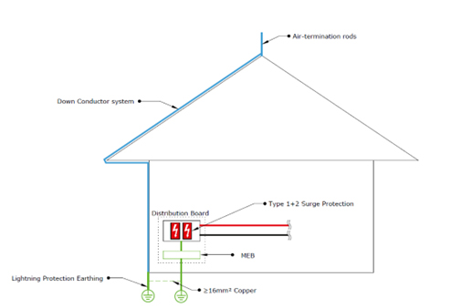
Figure 4: Mitigation of direct lightning current entering the electrical system.
Induced surges from lightning events are a common occurrence in South Africa. As mentioned previously, these can be caused by lightning strikes up to 2km away from the structure. As a minimum, it is recommended to then install at least a Type 2 device as these induced surges are represented with the 8/20µs test waveshape.
With the recent situation in South Africa, where we experience frequent load shedding, the switching of supply from the grid causes what is commonly referred to as “Switching Surges”. These switching surges are also described as impulses with waveshape like that of the 8/20µs test waveshape, and therefore the installation of Type 2 devices can prevent some of the damaging effects of switching surges as well.
In short, it is then required to install a Type 1+2 device if the structure has an existing external lightning protection system. If there is no external lightning protection system, it is recommended to install at least a Type 2 device to prevent the common induced surge damages.
A common installation error noticed within electrical installations in South Africa, is that installers only install a single pole Type 2 device between the live conductor and earth. As per SANS 10142-1, it is required to have the SPD installed on both conductors, with connection from Live to Earth and Neutral to Earth. If the SPD is only installed between live and earth, the neutral can still be exposed to potential differences caused by surges and may result in sparking between parts in the electrical system at equipment. In addition to this option, a “TT” configuration, also referred to as a 1+1 for single phase or 3+1 for three phase systems, makes the connection from live to neutral with a standard SPD and with a special “Spark Gap” module from neutral to earth. Advantages include avoiding nuisance tripping due to leakage currents.
Another point to consider is the size of the conductor used to install an SPD. The minimum size of conductor is indicated in the installation instructions from the manufacturer but will start with a minimum of 6mm² copper for Type 2 devices and 16mm² copper for Type 1+2 devices, in line with minimum requirements in SANS 10142-1 by means of SANS 62305-4. Further to this, the standard also stipulates that the maximum length of conductors should not exceed 0.5m from the live or neutral terminal to the earth bar. This means the total length of conductor used (live + earth or neutral + earth) may not exceed 0.5m. Certain manufacturers, however, give allowance to a total of 1m. Exceeding this length, causes a significant drop in performance of the surge protection concept, resulting in less overall protection of the electrical system. This is mainly due to the additional length causing higher potentials between lines during surge events, possibly leading to damage to equipment unable to withstand these potentials. A typical illustration of such installation length is shown in Figure 5.
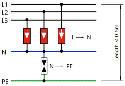
Figure 5: Illustration of maximum cable lengths and configuration of TT-systems.
To conclude, the application of surge protection for electrical systems in lightning prone countries such as South Africa is important. By understanding the risks involved, as well as the basics of SPD classifications, ratings and installation techniques, the installation of these devices becomes easier to justify and execute.
Enquiries: www.dehn-africa.com