

High voltage insulated ac cable systems making use of legacy Fluid Filled and modern Solid Dielectric extruded XLPE designs have been utilised in South Africa for HV distribution systems of voltage rating from 25,4 /44 kV up to 76/132 kV. Limited Paper Insulated Lead Extruded PILE mass impregnated non draining cable designs have also been utilised in systems above 19/33 kV rating. The highest insulated cable system rating installed in this country is 400 kV ac and no high voltage dc cables have as yet been installed locally.
 There is no argument that the higher the voltage rating, the more important the requirement for a reliable insulated cable system. This is illustrated by the fact that there is a drastic increase in the cost of high voltage systems when compared to medium voltage (MV) installations. This increase in cost relates not only to the higher manufacturing cost of the cables and the special accessories which are used, but also to the cost of the system design, installation and jointing practice, specialised skills required and the nature of commissioning testing after installation.
High voltage cables are designed with higher electrical stresses when compared with MV cables, which, can be up to 8 kV/mm at the conductor screen and 4 kV/mm at the insulation screen as compared to a typical operating stress of 2 kV/mm and 1 kV/mm respectively in MV cables. Higher stressed insulation systems translates to more sophisticated materials with higher breakdown strength and lower levels of contamination, therefore the need for more stringent quality control from the insulation system manufacturer as well as the cable manufacturer.
Accessories need to be designed to operate at increased stresses at the insulation interface when compared with MV accessories, calling for specialised materials, design and manufacturing processes and the need to test each insulation system of a pre-moulded joint and termination prior to shipment.
Cable manufacturers generally conduct system type tests in order to approve cable types together with a range of fitted accessories for the largest cable cross section conductor and highest rated voltage in the range of manufacture, which is not normally a requirement for MV cables.
On site testing
Tests conducted prior to energising the system
There are in essence two main categories of testing, namely Commissioning tests and Maintenance tests. Commissioning tests are conducted on newly installed cable systems or systems which have undergone repair work and involve overvoltage testing as opposed to a no load soak test, which in the past represented the only practical method to test HV cable systems prior to placing a feeder under load. These tests are done in order to confirm that the system performs as per the specification or set requirement and also to set a baseline against which the results of future tests may be measured. Newly installed systems usually represent the source of the majority of problems post installation as the intersection points are also the weakest points of a cable system. In the event that problems are detected under overvoltage test conditions, using Partial Discharge as a diagnostic tool, these issues may be addressed prior to placing the system in service and under load.
Maintenance testing is carried out on existing installations at the user’s discretion in order to assess potential deterioration or problem areas such as the onset of partial discharge, in comparison to commissioning test results. Maintenance testing is currently carried out rather as the exception than the rule.
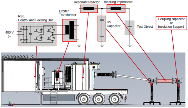
Modern mobile ac resonant test systems allow for overvoltage testing at what is regarded as near system frequency (20 to 300 Hz), thereby closely matching the electrical stresses which cable systems would be subjected to at 50 Hz. Such test systems from reputable manufacturers such as HiVolt and Phenix are used extensively around the world for testing capacitive loads, particularly power cables. Popular models are available for example in the 260 kV/83 A size range, capable of testing up to 400 kV cable systems and allowing for series connection of separate test units for increase test voltage or parallel connection for increased power, generally for longer cable routes or a less common arrangement being a combination of series and parallel connections.
Alternative overvoltage tests methods have been made possible with advancement in technology and are being employed or evaluated on a lesser scale in some countries, which includes Damped AC and Very Low Frequency (VLF) methods. Some work is currently being done in Cigré to set test criteria for these newer technologies as voltage levels and test durations requirements differ to those of near power frequency tests.
The range of tests which are normally required to be done in line with SANS IEC 60840 on installed HV cable systems are as set out below, together with the requirements of such tests. It is important to note that some distribution systems are of a lower voltage rating than the cable rating, for reasons of future expansion by example. Such systems must be tested in line with the rated voltage of the installed cable unless specifically agreed with the user.
Preparation for HV system testing requires that the special metallic sheath bonding arrangements normally not associated with MV systems be re-configured in order for testing to be done per single core cable and subsequently re-configured for the installed system.
ac Over Voltage Test
An overvoltage test is carried out with the aim of establishing the ability of the cable system to withstand a predetermined voltage for a predetermined period. The test waveform is required to be substantially sinusoidal and the frequency shall be between 20 Hz and 300 Hz. It should be noted that Cigre and IEC have been doing work on accepting lower frequencies (down to 10 Hz) for extra-long lengths of cable.
The voltage needs to be raised gradually to 1.7 U0 and then be maintained for 1 hour between the conductor and metallic screen/sheath.
The SANS 60840 standard allows for an alternative test whereby a voltage of U0 may be applied for 24 hours. This test, which is commonly referred to as a “Soak” Test is not recommended as potential defects may not show up under normal operating voltage. .
The criteria for a successful test is that no breakdown of the insulation shall occur.
Table of Test Voltages to SANS 60840
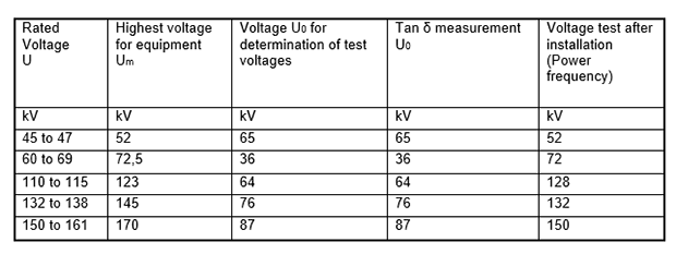
For extra high votlages SANS 62067 applies and the table below indicates the relevant test voltages

Partial Discharge Test
Potential defects in HV cable systems are by nature not gross defects such as potentially encountered in MV cable systems and as such, the partial discharge detection method is an extremely useful tool for the detection of subtle HV system defects. The test is be carried out in generally accordance with IEC 60885-3. A maximum PD level of 10 pC is applicable for laboratory tests but for on-site tests, the PD requirements are evaluated by experienced test teams through analyses of background noise, PD patterns, PD levels, etc.
The test involves the application of voltage which is raised gradually to a level of 1.7 U0 for 10s to trigger PD inception and then gradually reduced to 1.5 U0 at which level the detectable discharge should not exceed the declared sensitivity. PD detection systems such as the Omicron MPD600 is often employed in such tests and the detected Partial discharge patterns are used in determining the cause and location of potential problems.
Tan Delta (Loss Factor) Measurement
The Loss Factor measurement is used to judge the quality of an insulation system. Insulation materials are characterised by the properties of relative permittivity εr as well as the dielectric loss factor tan δ, both of which factors are depended on frequency, temperature and magnitude of applied electric stress. Relative permittivity is a measure of the electric polarizability of a dielectric as compared with the permittivity of free space (vacuum), being 1. Relative permittivity is a crucial property of the insulation material which determines the capacitance of a cable.
Loss factor measurements should be compared for the same cable system under the same or similar temperature, voltage and frequency test conditions. The TANDO 700 system is an example of a measurement system used for the determination of the loss factor.
Sheath Integrity Testing
High voltage cables have a covering of a semi-conductive material such as graphite paint or extruded semi-conductive material and are tested for sheath voltage withstand during manufacture. Where an after installation test of the over-sheath is performed, a dc voltage of 10 kV is applied between the underlying metallic layer such as Corrugated Seamless Aluminium and the outer semi-conductive covering for a period of 1 minute. No breakdown of the over-sheath shall occur during the test.
Contact resistance for earth and bonding connections (including link disconnecting boxes)
This test is done at the completion of all other tests in order to verify that the metallic screen bonding system is properly connected and grounded as required. Conductor resistance is measured over every contact using a micro ohmmeter and the resistance value corresponding to the conductor size should not be exceeded. The earth Resistance must not exceed 5 Ω outside substation and 3 Ω inside substation or as specified by the client. This will include sheath bonding contacts.
Positive and Zero sequence impedance measurements
Relevant Impedances may be measured on request of the user. Often high voltage cables are provided as 3 single cores. Because of the routing of the cables every core is not necessarily equal in length. Additionally, one of the cores can pass closer to metal objects or different ground resistances and this can cause varying impedances on each of the phases. During operation a phase shift can occur or worse during fault conditions a 90 or 270 degree phase shift is even possible. Therefore, the test is performed to ensure that the impedances are near equal and these effects are minimised. The test is performed by applying an AC power source and using impedance measurements to determine the values of the various impedances is obtained.
On Load Testing
Metallic sheath current measurements
These measurements are done in order to confirm the bonding design. All bonding lead currents are measured at every crossover box and or termination screen using a current transformer (CT) and current meter. All Current should be less than the protection level settings in order to prevent false trips and readings should be verified against the system design.
Sheath standing voltage measurements
These tests are done in order to verify the metallic sheath bonding design. Residual voltage on the cable sheath will be measured using a voltage divider and a voltmeter.
Enquiries: rendani.mutepe@aberdare.co.za