12
Mechanical Technology — August 2013
⎪
Proactive maintenance, lubrication and contamination management
⎪
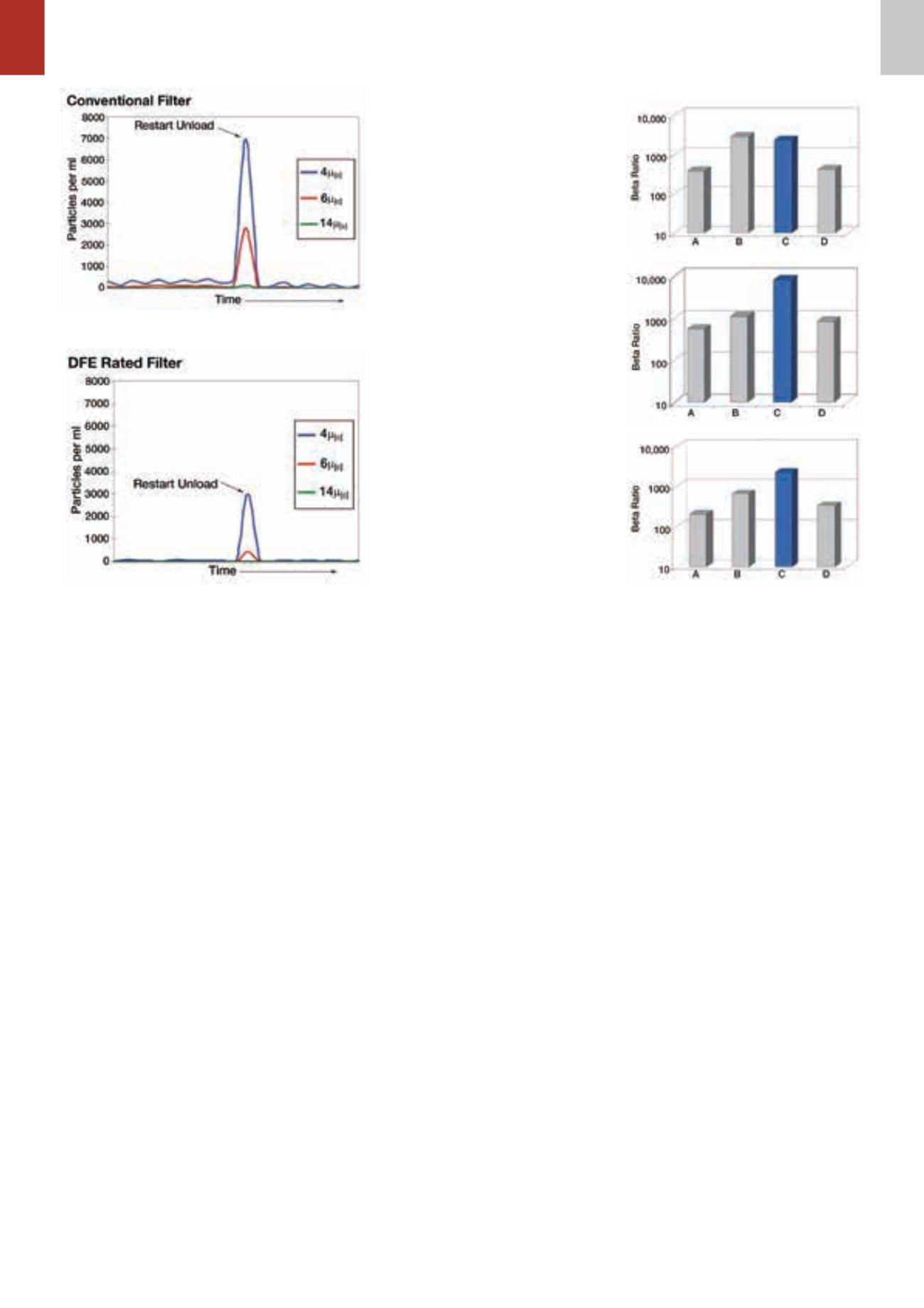
Figure 6: A comparison of the filter
performance of similar elements from dif-
ferent manufacturers and Hy-Pro’s DFE-
rated filters: (a) results of the ISO 16889
multi-pass test, expressed as a time-
weighted beta ratio; (b) the time-weighted
performance of the same elements tested
according to the DFE multi-pass test; (c)
particle counts taken during flow changes
that were isolated and averaged to yield a
beta ratio during transient flow.
particles counted after the conventional
filter increased by a factor of 20, and
associated ISO filter codes increased
fourfold for 4,0 and 6,0
µ
m particles.
During restart tests, no contaminant
is injected, so any particles measured
were already in the system or were
released by the element (unloading).
The result is a temporary state of highly
contaminated fluid because the filter
element did not properly retain the dirt.
The DFE-rated element, in this case a
Hy-Pro Element 3, also shows evidence
of unloading, but the effect is smaller
and retention efficiency higher.
The conventional element unloaded
seven times more particles greater than
6,0
µ
m and 35 times more particles
greater than 14
µ
m, compared to the el-
ement designed for dynamic conditions.
Comparing ISO and DFE tests
To compare filter performance under dif-
ferent test conditions, Hy-Pro examined
similar elements from different manufac-
turers. Figure 6 (a) shows results of the
ISO 16889 multi-pass test, expressed
as a time-weighted beta ratio. Element
B has the best capture efficiency in the
constant flow test, and all the elements
tested true to their catalogue beta ratios
of
β
5
(c)
> 200 or 1 000.
The next graph, Figure 6 (b), shows
the time-weighted performance of the
same elements according to the DFE
multi-pass test. The two tests were run
similarly, except for the flow rate. Here,
flow cycled up and down through the
element’s operating range to simulate
a real-world hydraulic system’s duty
cycle. The time-weighted beta ratio
for Elements A and B were below the
ISO-rated beta ratio, while Elements C
(Hy-Pro) and D performed true to rating.
The third graph, figure 6 (c), shows
particle counts taken during flow chang-
es that were isolated and averaged to
yield a beta ratio during transient flow.
Because the DFE test shows filter-
element performance is worst during
flow changes, isolating these sequences
can predict performance in dynamic
flow systems. This graph shows how
systems with cyclic flow affect overall
filter performance.
Element B had a beta ratio exceed-
ing
β
7
(c)
> 2 000 when tested per ISO
16889. However, the same element
during variable flow had a beta ratio
less than
β
7
(c)
> 100. Element C, the
Hy-Pro element, had a beta ratio that
exceeded
β
7
(c)
> 800 and was the only
one to achieve a beta ratio greater than
1 000 during this test.
Relying solely on ISO 16889 to
predict filter-element performance in
systems with dynamic flow conditions
causes OEMs to select filters without all
the available information. ISO 16889,
the current industry standard test for
hydraulic and lubrication filter perfor-
mance, is a good tool for predicting
performance of off-line filters and steady-
state circulating systems. But it does
not accurately represent the stress of a
hydraulic circuit with varying flow rates
or cold start conditions. Without DFE
testing, it is difficult to truly predict actual
filter performance in a dynamic system.
A total system cleanliness
approach
Selecting the right filter for an applica-
tion is important, but it’s just one part
of the whole picture. Developing a total
system cleanliness approach to control
contamination and care for fluids ulti-
mately results in more reliable plant
operation and saves money. Steps to
total system cleanliness include:
• Evaluate the fluid cleanliness re-
quirements of all hydraulic and
lubrication systems.
Figure 4: The cold-start performance of conventional
filters subjected to a restart test.
Figure 5: The cold-start performance of DFE-rated
filters subjected to the same restart test as that shown
in Figure 4.
• Establish an oil analysis programme
and schedule.
• Establish a baseline and target fluid
cleanliness for each system.
• Insist on specific fluid cleanliness
levels for all new, purchased fluids.
• Filter all new fluids upon arrival and
during transfer.
• Seal all reservoirs and bulk tanks.
• Install high quality particulate and
desiccant breathers.
• Enhance air and liquid filtration on
existing systems wherever suitable.
• Use portable or permanent off-line
filtration to enhance existing filtra-
tion.
• Improve bulk oil storage and han-
dling during transfer.
• Remove water.
This approach might seem expensive
and laborious, but studies have shown
that the cost of proper contamination
control and total systems cleanliness is
less than 3% of the cost of contamina-
tion not kept under control.
q
ISO 16889 Multi-Pass
DFE Multi-Pass
Real-Time Flow Change


